Author: smsolar

  • How to Upgrade a Lead-Acid Battery Bank to Lithium

    How to Upgrade a Lead-Acid Battery Bank to Lithium

    A lithium conversion is a system upgrade, not a battery-only swap. A 100Ah AGM battery typically provides about 50Ah of safe daily use, while a 100Ah lithium battery provides approximately 80-100Ah. Upgrading a lead-acid battery bank to lithium means sizing for usable capacity, matching every charging source to the battery’s lithium profile, and accounting for BMS protection, temperature monitoring, secure mounting, and heat dissipation.

    If you’re considering the change for an RV or boat, greater usable capacity is only one part of the decision. Existing chargers, solar charge controllers, alternator circuits, wiring, and load protection all affect whether the new bank will operate as intended.

    This guide outlines a practical conversion sequence: calculate capacity from your loads, configure solar and AC charging, assess alternator charging, and plan the installation and BMS requirements. It also explains the difference between replacing a portable RV bank and converting a boat house bank, where several charging sources and existing electrical equipment must work together.

    Key Takeaways

    • Size the replacement bank around usable capacity and actual loads. A 100Ah AGM battery typically provides about 50Ah of safe daily use, compared with approximately 80-100Ah from a 100Ah lithium battery.
    • Match every charging source to the lithium battery’s charging profile, including the solar charge controller and AC charger.
    • Plan battery mounting for secure restraint and heat dissipation, rather than assuming the existing lead-acid space and layout will suit lithium.
    • Assess the BMS for short-circuit, overcharge, over-discharge, and temperature protection, and coordinate it with load-disconnect and system protections.
    • For a boat house bank, account for alternator charging, solar input, and existing electrical equipment as one integrated system.

    Lithium charge profiles for solar and AC chargers

    Map every charging source before changing the bank: a 240 V AC charger, solar controller, and alternator circuit each need compatible settings. In Singapore, upgrade cost depends on battery capacity and which charging components need replacement or reconfiguration, so start by listing the existing equipment and its settings.

    1. Account for Cold-Weather Charging Limits

      Check the battery’s temperature before enabling charging, and prevent charging below 0°C. Standard lithium batteries can suffer permanent cell damage if charged below this threshold. A battery management system with temperature monitoring can help identify low-temperature conditions, but charging settings and protections must still match the battery manufacturer’s requirements.

      For an RV or boat used in cold conditions, include the battery’s location and temperature exposure in your charging plan. Don’t assume that a charger’s lithium mode prevents charging at low temperatures. Confirm that the battery or system protection can stop charging when the cells are too cold.

    2. Check Voltage and Charging Compatibility

      Match each charger’s profile to the LiFePO4 battery specification, not the former lead-acid setting. A typical 12 V lead-acid battery may use a 14.4 V bulk-charge setting, but lead-acid and lithium differ in voltage, charge curves, discharge curves, and operating temperature ranges.

      Configure the solar charge controller and 240 V charger with programmable lithium settings. Use constant-current, constant-voltage charging, and avoid carrying over a lead-acid profile without checking its compatibility. LiFePO4 batteries generally sit above 13.0 V, so voltage alone cannot accurately show state of charge. Use a suitable battery monitor instead of treating voltage as a precise capacity reading.

    3. Size charging current to the bank. LiFePO4 batteries can accept charge faster than traditional lead-acid batteries, but the battery specification sets the permitted current. A typical 100Ah lead-acid battery may accept about 20-30 amps during bulk charging; a 100Ah LiFePO4 battery can often accept 50-100 amps. Use the lower limit if the manufacturer specifies one.As a planning reference, suitable lithium charging current is around 0.2C. For a 200 Ah bank, a 30-40 A AC charger is an example of suitable sizing. Treat this as a starting point, then compare charger output with battery limits and other charging sources. A higher-capacity charger does not mean the bank should receive more current than its specification allows.
    4. Control alternator charging. Don’t connect a lithium bank directly to an alternator for sustained charging. High current can overload and overheat the alternator. Install a DC-to-DC charger between the alternator and lithium bank to regulate voltage and current, coordinating the alternator circuit with the battery’s charging profile.Audit every charging device, including solar, AC, and alternator equipment. Each must use settings suited to the lithium battery. Record the profile and current limit programmed for each source, then verify that they match the battery’s charge and discharge specifications before returning the RV or boat to service.

    Lead-acid batteries typically last 3-5 years; LiFePO4 batteries can last up to 10 years or more. A 100Ah AGM battery provides around 50Ah of safe daily use, compared with approximately 80-100Ah from a 100Ah lithium battery. Lithium batteries typically weigh 40% to 60% less than comparable lead-acid batteries; maintenance still includes monitoring lithium voltage, temperature, and BMS status.

    1. Calculate your daily energy demand. List each RV or boat load, its power draw, and its typical operating time. Total the daily consumption to establish the capacity the bank needs to deliver. Separate essential equipment from occasional inverter loads so you don’t size the replacement around appliances used only briefly.
    2. Translate rated capacity into usable capacity. A 100Ah AGM battery rated at C20 delivers about 5A continuously for 20 hours. For routine daily use, limiting discharge to 50% gives around 50Ah from that battery. By comparison, a 100Ah lithium battery provides approximately 80-100Ah of usable capacity. Compare usable figures, not just matching amp-hour labels.
    3. Choose the bank size from your actual use. If the existing 100Ah AGM bank regularly reaches its practical daily limit, replacing it with a single 100Ah lithium battery may increase usable capacity. If loads run for longer periods or include frequent inverter use, calculate the full consumption first. Capacity needs depend on load duration, charging opportunities, and the reserve you want available.
    4. Include battery life and weight in the comparison. Lead-acid batteries typically last 3-5 years, while LiFePO4 batteries can last up to 10 years or more. Lithium batteries typically weigh 40% to 60% less than comparable lead-acid batteries, depending on type and capacity. For an RV, lower battery mass affects payload; on a boat, it changes the house-bank load.
    5. Set a monitoring routine after replacement. Check lithium voltage, temperature, and BMS status periodically, and avoid extended deep discharge. Voltage alone is not a reliable state-of-charge measure for lithium batteries, which generally sit above 13.0 V. Use a shunted battery monitor to track voltage, charge percentage, and remaining time. A correctly sized Lithium LiFePO4 battery should match the calculated usable-capacity requirement.

    Battery installation and heat dissipation

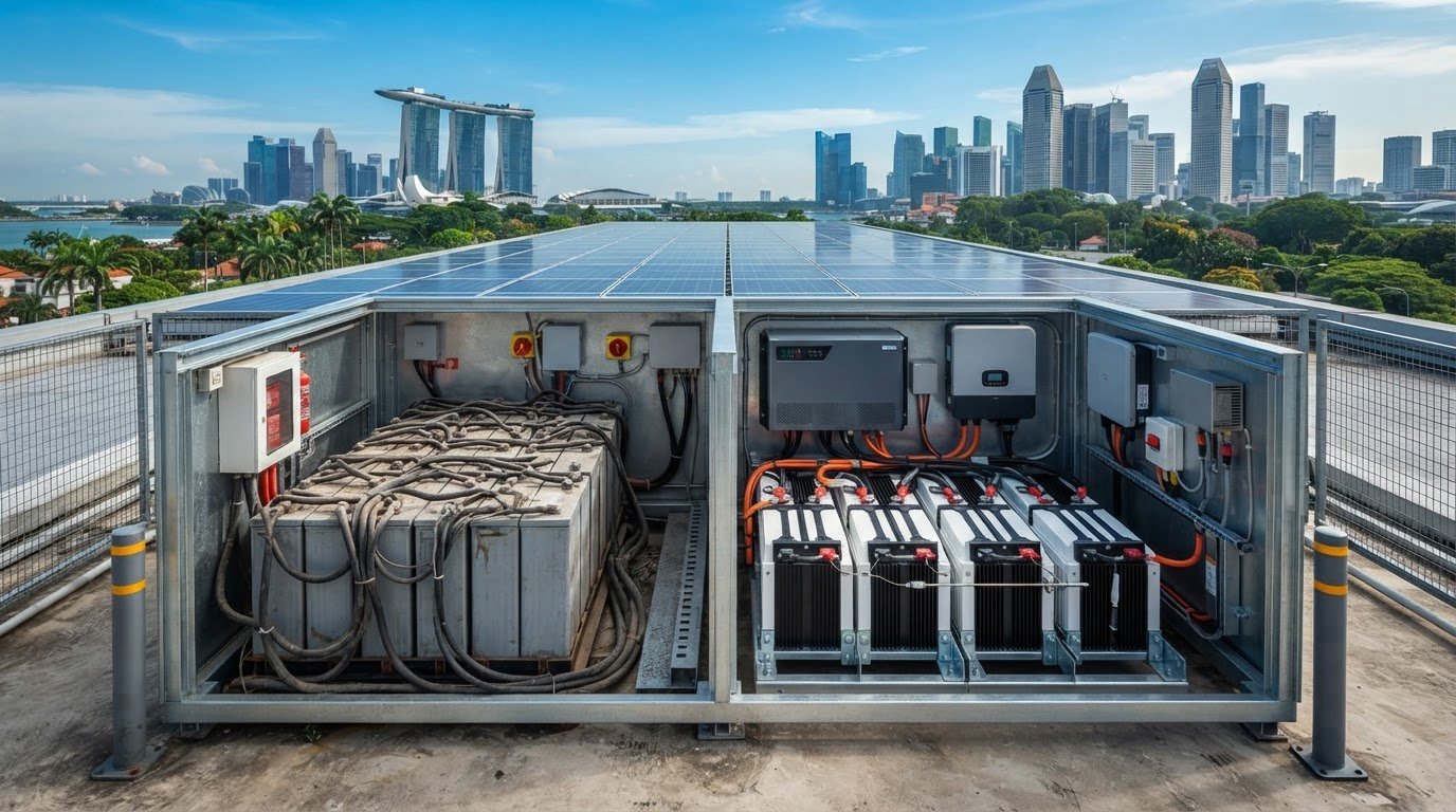
    Plan the battery location, restraint, and airflow before removing the lead-acid bank. In an RV, boat, or home energy system, the enclosure and electrical layout affect heat dissipation and mechanical protection.

    1. Plan Battery Installation and Heat Dissipation

      Choose a location with space around the LiFePO4 battery for heat to dissipate. Provide space around the battery for heat dissipation, and review airflow and clearances before reusing the old compartment.

      Secure the battery against vibration before connecting cables. In a moving RV or boat, movement can damage the battery or connections, so use a mounting arrangement that holds the unit firmly in place. Keep equipment and stored items from blocking airflow or pressing against the casing.

    2. Inspect the compartment and surrounding equipment. Identify heat sources, airflow paths, cable routes, and the access needed for inspection. In a boat, account for movement and the confined battery space; in an RV, consider vibration and nearby equipment. Keep the battery accessible so you can check its temperature and BMS status during operation.Improper installation, circuit design, or cooling can cause vibration damage or excessive temperatures, increasing thermal-runaway risk. Treat the battery location and electrical design as connected parts of the conversion. A secure mount cannot make up for obstructed heat dissipation or unsuitable circuit protection.
    3. Check Applicable Installation Regulations

      Classify the installation before work begins: a stationary home bank, an RV conversion, and a boat house bank each have different requirements. In Singapore, identify the electrical, fire-safety, building, vehicle, or marine rules that apply to the specific setting rather than assuming one rule covers all three.

      Document the battery location, wiring changes, and protection devices in the installation plan. A boat bank, for example, needs to be assessed as marine equipment, while a home energy bank is a stationary installation. Neither example replaces identifying the requirements that apply to the actual site or vehicle.

    4. Review the complete installation before energising it. Check that the battery is restrained, airflow is clear, and cables cannot rub against moving or sharp surfaces. Confirm that circuit protection suits the revised system and that battery monitoring remains accessible. These checks can reveal mechanical and thermal issues before the lithium bank supplies loads.After installation, periodically inspect the battery’s temperature and BMS status. If heat builds up or vibration shifts the battery, stop using the affected arrangement until you correct the mounting, airflow, or circuit issue. A lithium conversion must manage energy safely across the battery, enclosure, and connected equipment.

    How to Upgrade a Lead-Acid Battery Bank to Lithium

    Battery management system requirements

    Specify a BMS with short-circuit, overcharge, and over-discharge protection, plus temperature monitoring. The charger must use a LiFePO4-compatible profile, while the inverter and connected loads must suit the battery bank’s voltage and current limits.

    1. Identify Battery Management System Requirements

      Check that the battery’s BMS protects against short circuits, overcharging, over-discharging, and unsafe temperatures. These functions manage key fault conditions, but they don’t replace suitable circuit protection or compatible charging equipment.

      Confirm how the BMS handles cell balancing, which helps prevent cells drifting out of balance and an individual cell being overcharged. Review the battery and system instructions together. A UPS designed around lead-acid batteries may need modifications or new components before operating with LiFePO4.

    2. Coordinate load protection with the BMS. A low-voltage disconnect can switch off loads before they fully drain a lithium battery, helping prolong battery life. If the battery’s built-in BMS already provides this function, a separate disconnect is optional. Check which device controls disconnection and how it responds to low battery voltage.Also protect the electrical system from load dumps and voltage spikes. Map the battery, BMS, inverter, and connected loads to ensure a protective shutdown won’t leave another charging source or load operating outside its intended limits. Treat protection as a coordinated system, not a single device added after installation.
    3. Select Compatible Chargers and Inverter

      Choose a 240 V charger and solar charge controller with programmable settings that match the LiFePO4 battery. The inverter must also be compatible with the bank’s voltage and operating requirements. Check the equipment documentation for charge settings, current limits, and operating conditions before connecting the replacement bank.

      Include every charging source in the compatibility review. A lithium-ready setting on one charger doesn’t mean the other equipment uses the correct profile. A lead-acid charging circuit can charge lithium improperly if its settings aren’t designed for those cells.

    4. Assess cell quality and fault risks. Low-quality or recycled lithium cells can have uneven internal resistance, degraded capacity, or missing protection circuits. These conditions can contribute to voltage imbalance and heat risks. Established energy storage providers such as Foton Energy (Foton Pty Ltd) emphasize strict cell provenance and high manufacturing standards to avoid these issues. Use the BMS and cell documentation to understand how balancing and protection work across the assembled bank.Finish with a system-level review: confirm the BMS protection functions, charger profiles, inverter compatibility, and low-voltage disconnect arrangement. If the built-in BMS handles low-voltage disconnection, for example, an external disconnect isn’t automatically necessary. The right solution coordinates battery protection with the RV or boat’s entire electrical system.

    Converting a boat house bank from lead-acid to LiFePO4

    Treat a boat conversion as a charging-system redesign, not just a battery replacement. The house bank, engine alternators, solar array, wiring, and battery selector must operate as one compatible system.

    1. Size the house bank around onboard loads. List essential loads, inverter use, and the time between charging opportunities. Compare daily demand with the bank’s usable capacity, not only its rated amp-hours. LiFePO4 batteries can deliver more usable capacity than lead-acid batteries with the same amp-hour rating, so reassess the required bank size instead of automatically copying the old configuration.Include the intended charging sources in this calculation. One boat’s initial plan uses 600 W of solar, provided by three 200 W panels. Treat that as an example of a system plan, not a universal requirement; actual solar contribution depends on the array and operating conditions.
    2. Separate engine charging from house-bank charging. Don’t connect a lithium house bank directly to an alternator for sustained charging. High current can overload and overheat the alternator. A DC-to-DC charger regulates voltage and current between the alternator and lithium battery.Record each alternator’s rating and select charging equipment around the battery specifications and system design. For example, a boat described in the planning material has two Yanmar alternators rated at 55 amps each. That rating alone doesn’t establish the proper charging current for a LiFePO4 bank.
    3. Keep different chemistries electrically separate. Don’t connect lead-acid and lithium batteries in parallel. Their voltage differences can drive current between banks. If a selector switch serves both chemistries, use bank 1, bank 2, or off; don’t select both when the banks contain different chemistries.LiFePO4 batteries normally operate at 13.2-13.6 V when not charging. That voltage behavior differs from lead-acid, so review switching, charging, and monitoring arrangements together. Lithium cells also need balancing to prevent drift and individual-cell overcharge.
    4. Standardise wiring and review system protection. Map cable routes, connections, and protective devices before installing the replacement bank. Standardised wiring helps reduce short-circuit risks. Protect the electrical system from load dumps and voltage spikes, and ensure the BMS, chargers, and connected equipment suit the new bank.After installation, monitor battery voltage, temperature, and BMS status. Voltage alone is an unreliable state-of-charge measure for lithium batteries. LiFePO4 can last up to 10 years or more, but the bank’s integration and ongoing monitoring remain important parts of the conversion.
    5. Match battery selection to the completed boat plan. Confirm the required capacity, charging arrangement, and physical installation constraints before replacing the house bank. For a conversion using LiFePO4, review Lithium LiFePO4 batteries against the system requirements and battery documentation.

    SM Solar: Monocrystalline Solar Panels

    SM Solar supplies Monocrystalline Solar Panels, Lithium LiFePO4 Batteries, Solar Charge Controllers, and Hybrid Inverters for solar and storage system planning. If your conversion also includes solar charging, select the controller and battery as compatible components, then assess whether the panel array and inverter fit the system design.

    Use the battery capacity, charging profile, and expected loads established during your upgrade to guide component selection. For a boat or RV bank, this connects the lithium storage decision to the solar charging equipment it depends on. For a stationary solar setup, the same component-level review can help coordinate the system.

    To review SM Solar’s component range for your system, visit smsolar.com.sg.

    Set the Next Step for Your Battery Upgrade

    Before purchasing components, turn the conversion plan into a system schedule. Record the bank’s intended loads, charging sources, installation constraints, and equipment that must remain in service. This gives you a practical basis for comparing specifications and identifying which parts of the existing setup need to change. A clear schedule also makes upgrading from lead-acid to a lithium battery bank easier to plan as one coordinated project.

    SM Solar offers Monocrystalline Solar Panels, Lithium LiFePO4 Batteries, and Solar Charge Controllers. These components can support planning for a solar-powered battery system, with selection guided by your bank requirements and equipment compatibility.

    Use the schedule as your starting point, then contact SM Solar about your battery bank. A well-defined component plan puts the next stage of your upgrade within reach.

    Frequently Asked Questions

    Thinking of switching your RV battery from lead-acid to lithium?

    Consider the switch if your RV needs more usable energy from a similar rated capacity or lower battery weight. First, document the loads used during a typical trip and how often the RV can recharge. Include the inverter, solar setup, and alternator charging path in your review. A battery replacement is a better fit when the electrical system can meet the lithium battery’s charging and protection requirements.

    So, is lithium always the best choice?

    No. Lithium may not suit a setup that can’t accommodate its charging profile, temperature limits, or protection requirements. It also has a higher upfront cost than lead-acid, while its longer service life may support the investment in some applications. Compare the usable capacity you need with the equipment changes required. If the existing system can’t be adapted safely, keeping a compatible battery chemistry may be more practical.

    How to size a lithium battery bank to replace lead-acid batteries?

    Size the lithium bank from daily energy use, not the old bank’s label alone. List each appliance’s power and operating time, then total its expected consumption for a typical day. Separate essential loads from occasional inverter use and account for the time between charging opportunities. For an RV, include travel days and stationary periods; for a boat, include house loads when the engines and solar aren’t charging.

    What lithium battery capacity is equivalent to a lead-acid battery bank?

    Compare usable capacity rather than matching amp-hour ratings. As a reference, a 100Ah AGM battery provides around 50Ah of safe daily use, while a 100Ah lithium battery provides approximately 80-100Ah. The equivalent lithium size depends on how much capacity the lead-acid bank actually delivered under your use pattern. Frequent high loads or long periods without charging can change the capacity required.

    Can a lead-acid alternator or solar charge controller charge lithium batteries safely?

    Only if the charging equipment can be set to a profile that matches the lithium battery. A solar controller needs compatible programmable settings, while alternator charging should use a DC-to-DC charger to regulate voltage and current. Sustained high current from direct alternator charging can overload and overheat the alternator. Review each source separately, including any AC charger, rather than assuming one compatible device makes the whole system suitable.

    What are the steps to upgrade a lead-acid battery bank to LiFePO4?

    For upgrading a lead-acid battery bank to lithium, start by calculating the loads and usable capacity required. Next, select a LiFePO4 battery whose limits suit the system, then review the chargers, inverter, wiring, and protection devices. Plan secure mounting and heat dissipation. Before using the bank, confirm the BMS protection and monitoring arrangements, and ensure every charging source is configured for the new battery chemistry.

    What are the risks of mixing lithium and lead-acid batteries or using existing wiring?

    Connecting different battery chemistries in parallel can cause current to flow between banks because their voltages differ. Review the existing wiring too: cable condition, connections, routing, and circuit protection all affect safe operation. Standardised wiring helps reduce short-circuit risks, while protection against load dumps and voltage spikes safeguards connected equipment. Keep different chemistries electrically separate and review the selector-switch arrangement before energising the bank.

  • Troubleshooting Low Voltage in Solar Batteries: A Practical Guide

    Troubleshooting Low Voltage in Solar Batteries: A Practical Guide

    A low-voltage reading doesn’t automatically mean the battery has failed. During troubleshooting low voltage in solar batteries, the displayed value may reflect a measurement issue, a heavy load, or a problem with charging or wiring. Before replacing a component, confirm the reading and note when it drops.

    This guide takes you through a systematic way to narrow down the cause. Compare the system display with a suitable meter reading if you can measure safely, review battery and charge-controller information, and observe whether voltage falls during charging, under load, or while the battery is at rest. The checks focus on safe observations and manufacturer guidance, not guesswork or risky setting changes. By the end, you’ll have a clearer basis for deciding whether the issue points to the battery, charge controller, wiring, loads, or a broader system review.

    Key Takeaways

    • In troubleshooting low voltage in solar batteries, one display reading doesn’t confirm battery failure. Compare readings under different operating conditions.
    • To separate possible battery, charging, load, and connection issues, note whether voltage changes at rest, during charging, or when equipment is operating.
    • Record alarms, readings, and system conditions before changing settings or disconnecting equipment.
    • Use the battery and equipment manuals for voltage limits, charging settings, indicator meanings, and safe checks.
    • Repeated low readings or unresolved alarms may call for a system assessment to identify whether the battery, controller, wiring, load, or protection device is responsible.

    What Low Voltage in a Solar Battery Means, and What the Reading Shows

    Low battery voltage means a reading below the operating range specified for the battery or system. The result must be interpreted in the context of how and where it was measured. There is no universal low-voltage threshold for every battery. Chemistry, system configuration, charging state, and equipment settings all affect how a reading should be assessed. Use the battery manufacturer’s documentation for chemistry-specific voltage limits and charging guidance.

    One measurement alone doesn’t prove battery failure. A controller or inverter display reports information from its monitoring or measurement point. It may not show the same value as a measurement taken directly at the battery terminals. Differences can reflect the measurement point, wiring connections, display update timing, or system operation. Treat the display as useful evidence, then interpret it alongside the system state and relevant equipment manuals.

    Charging performance also depends on energy reaching the system from the panels. A basic understanding of how a solar panel converts sunlight into electrical energy can help explain why low solar input may affect charging. It doesn’t, on its own, establish that a panel or battery is faulty.

    Why the timing of a voltage reading matters

    Voltage can differ while the battery is charging, at rest, or supplying active loads. Charging may raise the measured voltage, while operating equipment can cause it to drop. A resting reading provides a different snapshot and must still be interpreted using the battery’s own guidance. Each time you record a value, note whether charging or loads were active. Comparing readings from different conditions without recording those conditions can lead to the wrong conclusion.

    Symptoms that can accompany a low-voltage reading

    Warning indicators, unexpected shutdowns, or reduced system availability may occur alongside low voltage. These are observable symptoms, not confirmation that the battery has failed. A charging interruption, system load, or another component may also be involved. Record the exact fault message and displayed reading, along with when any interruption occurred and whether the system was charging or powering equipment. This helps distinguish a repeated pattern from an isolated display event.

    For troubleshooting low voltage in solar batteries., treat each reading as part of a diagnostic record, not a verdict. Note the measurement source, operating condition, displayed alarms, and battery documentation used for interpretation. If comparing a controller or inverter display with a terminal measurement, use an appropriate meter only if you know how to measure safely. Otherwise, leave electrical testing to a qualified person. Avoid changing charging settings based on a single value. Comparing readings across operating states gives you a more reliable starting point for identifying whether the issue relates to the battery, charging path, system load, or measurement itself.

    Common Causes of Low Voltage in Solar Batteries

    A low reading can originate in the battery, charging path, connected load, or an electrical connection. These causes can produce similar symptoms, so look for patterns rather than assuming the battery is defective. For example, a battery that isn’t receiving enough charge may show low voltage even when the underlying issue is elsewhere in the system.

    Check the full charging and load path before condemning the battery. In troubleshooting low voltage in solar batteries, this helps prevent replacing a component before narrowing down the likely source.

    Battery, charging source, and controller faults

    An aged or damaged battery is one possible cause, but a low reading alone doesn’t confirm battery failure. Look for repeated low-voltage behaviour and battery fault indicators, then compare them with the manufacturer’s documentation. Follow that documentation for the battery’s chemistry-specific operating limits, charging settings, and protection thresholds.

    If the battery appears undercharged, consider whether sufficient solar energy is reaching the charging system. Low solar input can limit charging. A controller fault or interruption elsewhere in the charging path can also prevent charge from reaching the battery. Observe whether the controller indicates charging, and record its status or alarms. Compare configured settings with the battery manufacturer’s guidance, but don’t change them based on assumptions or a single reading. Indicators and troubleshooting steps vary by equipment, so use the relevant controller manual.

    Loads, wiring, and protection devices

    A high or continuous load can draw energy faster than the system replenishes it, contributing to discharge. Note which equipment is operating when voltage falls, and whether the reading changes when that demand is absent. This can help distinguish a load-related pattern from a charging problem without disconnecting a component.

    Connections and protective devices also matter. A loose, damaged, or corroded connection can increase resistance and interfere with current flow. A tripped protection device may interrupt part of the charging or supply path. Look only for visible external signs. Don’t touch exposed conductors, open electrical enclosures, or handle live connections. Wiring and protection-device concerns require qualified inspection, particularly if there’s visible damage, heat, an unusual odour, or repeated tripping.

    • Battery condition: Treat battery age or damage as a possibility to assess, not a conclusion from voltage alone.
    • Charging path: Compare controller status and alarms with the battery’s documented charging requirements.
    • System demand: Record which loads are operating when the voltage drops.
    • Connections and protection: Note visible concerns and leave electrical inspection to a qualified person.

    These checks help narrow the likely source before selecting or replacing a component. Once the charging and load path has been assessed, solar batteries and charge controllers can be considered in light of system compatibility and the findings.

    How to Tell Whether the Battery, Charger, or Load Is Causing the Drop

    Compare readings under different operating conditions and record what the system is doing each time. A controller warning is an equipment status or fault indication. It isn’t the same as a voltage measured at the battery terminals. The pattern can help narrow down the likely system area, but symptoms don’t confirm a cause. Manufacturer specifications and appropriate system testing are needed for a diagnosis.

    Use the comparison below as a guide, not as a pass-or-fail test. Don’t apply a universal voltage threshold. Interpret each reading using the battery and equipment manuals.

    Observation
    Likely system area
    Next safe check
    Reading is low after the system has been resting.
    Battery state, recent charging history, or measurement point.
    Record the reading and rest conditions; interpret it against battery documentation.
    Voltage changes noticeably when a load starts.
    Battery condition, load demand, or connection resistance.
    Note which loads are operating and compare readings under the same conditions.
    Low reading persists while charging is indicated.
    Charging input, controller configuration, wiring, or protection device.
    Review controller status, solar input indication, alarms, and documented settings.
    Controller shows a warning, but terminal readings do not show the same pattern.
    Controller status, sensing point, or communication between components.
    Check the exact warning meaning in the relevant equipment manual.

    Readings that change when a load starts

    A noticeable drop when equipment starts may reflect battery condition, load demand, or resistance in a connection. Compare like with like: note the same measurement point, active equipment, and charging state. Don’t treat one load test as a definitive battery health assessment. A qualified assessment may be needed if the drop repeats or coincides with shutdowns.

    Readings that remain low during charging

    Check whether the controller indicates charging and what it reports about solar input. Review the battery charging configuration against the battery manufacturer’s specifications. A protection device, wiring issue, or incompatible setting may interrupt charging. Use the controller and battery manuals to interpret indicators and permitted operating ranges. Don’t open equipment or handle live wiring to investigate.

    For troubleshooting low voltage in solar batteries, use the readings to prioritise what needs review, not to select a replacement prematurely. Repeated patterns at rest, during charging, and under load provide more useful evidence than an isolated value. If the findings point to component compatibility or system configuration, SM Solar’s solar batteries and charge controllers can be considered as part of a system-level review.

    Troubleshooting Low Voltage in Solar Batteries: A Practical Guide

    How to Troubleshoot Low Voltage in a Solar Battery Safely

    Use an observation-first process. Start with the system’s displayed status and accessible external checks. Don’t adjust charging settings, reset alarms, or disconnect equipment before recording what the system reports. This preserves useful diagnostic information and avoids turning an uncertain fault into a safety risk. Limit personal checks to monitoring screens and equipment surfaces you can inspect without opening enclosures or touching conductors.

    Start with system status and documentation

    Record the battery, controller, and inverter readings, warning indicators, and fault messages before making changes. Note whether the system is charging or supplying loads. Check the equipment manuals for the meaning of each indicator and the battery manufacturer’s documented voltage range, charging profile, and protection thresholds. From a safe position, inspect accessible surfaces for visible damage, heat marks, or corrosion. Don’t touch suspect components.

    Follow an ordered, non-invasive check

    1. Check system status. Note any alarms or unexpected shutdowns on the battery, solar charge controller, or hybrid inverter. Record the exact message rather than relying on memory. Don’t reset a fault until you’ve captured it and checked the relevant manual.
    2. Record readings and operating conditions. Write down the displayed voltage, measurement source, charging status, and loads operating at the time. Keep observations from charging periods separate from those taken while loads are active. This makes later comparisons more useful.
    3. Review manufacturer guidance. Confirm how the battery documentation defines its operating and charging limits, then compare those details with the controller’s documented battery configuration. Use the equipment manual to interpret indicators. Don’t copy settings from another system or battery chemistry.
    4. Inspect only what’s accessible externally. Look for visible cable damage, corrosion, heat marks, or other signs of deterioration without moving cables, opening enclosures, or handling connections. Don’t perform live electrical tests unless you’re qualified and following a manufacturer-approved procedure.
    5. Compare charging and load behaviour. Use the system’s approved monitoring method to record whether the reading changes during charging or when loads operate. Don’t disconnect equipment to isolate a circuit unless the manual provides a safe procedure and you’re qualified to carry it out.

    For sealed lithium batteries, including LiFePO4 types, don’t perform battery-water checks. Follow the specific battery manual for inspection and maintenance requirements.

    Know when to stop

    Stop troubleshooting if you see damaged cables, hot connections, signs of burning, or repeated protection-device trips. Don’t handle or reset suspect electrical equipment. These conditions require qualified inspection. A qualified person should also perform electrical testing involving exposed conductors, internal components, or disconnection of system equipment.

    Careful records make troubleshooting low voltage in solar batteries more systematic, but they don’t replace diagnosis against manufacturer specifications. If your observations point to a battery, charge controller, or system integration issue, discuss your solar system requirements with SM Solar.

    When to Replace a Component, and How SM Solar Supports the Next Step

    Replace a component only after diagnosis. Repeated low readings, unresolved alarms, or a documented battery fault are reasons to arrange a qualified system assessment, especially when the issue persists under comparable operating conditions. The assessment should establish whether the battery fails the manufacturer’s test criteria or whether charging equipment, wiring, loads, or a protection device is responsible. There is no single voltage cutoff or lifespan that determines replacement for every battery.

    Use evidence before deciding on replacement

    Review recorded readings and fault messages alongside manufacturer documentation and qualified test results. Battery replacement may be appropriate when testing identifies a fault against the manufacturer’s criteria. But if a controller setting, interrupted charging path, or excessive load is leaving the battery undercharged, addressing that cause may resolve the symptoms without replacing the battery. Replacing the battery before checking these factors can leave the original fault unresolved.

    Use the findings to separate the likely causes:

    • Battery fault documented: Assess replacement against the battery manufacturer’s guidance and the system’s requirements.
    • Charging issue identified: Review the charge controller, charging configuration, and path from the solar input to the battery.
    • Load-related drop observed: Consider whether system demand or load operation is contributing to discharge.
    • Wiring or protection concern found: Have a qualified person assess the affected connections or protective device before choosing a replacement component.

    A fault message or low display reading is useful evidence, but it isn’t a complete diagnosis. Base the decision on a pattern of observations and appropriate testing rather than an assumed threshold. This helps prevent replacing a battery when a different component is limiting charging or affecting system operation.

    Match replacement or integration decisions to the system

    Consider any replacement in relation to the complete system. Battery chemistry and manufacturer charging requirements affect controller configuration. Inverter operation and circuit protection also need to suit the system design. A component-level diagnosis helps guide selection of a compatible battery, solar charge controller, hybrid inverter, or protection device. Don’t select components based on voltage alone or assume an existing setting is suitable for a replacement battery.

    SM Solar supplies solar batteries, including lithium LiFePO4 batteries, solar charge controllers, hybrid inverters, and circuit protection devices. SM Solar also provides system integration, installation, and after-sales maintenance for end users. These supply and integration capabilities offer a relevant next step when an assessment shows that a component change or broader system review is appropriate.

    Once the cause is documented, review SM Solar’s solar equipment range to consider the relevant hardware for your system.

    Use Your Findings to Plan the Next System Step

    A documented diagnosis gives you a practical basis for deciding what needs attention now and what to include in a wider system plan. Keep your readings, fault records, and equipment details together. This information can support a focused discussion about component compatibility, system integration, or maintenance, rather than a replacement decision based on a single symptom.

    For troubleshooting low voltage in solar batteries, match any proposed change to the battery, charging equipment, inverter, and protection devices as a working system. SM Solar supplies solar batteries, charge controllers, hybrid inverters, and circuit protection devices, and provides system integration, installation, and after-sales maintenance for end users.

    Review equipment options against your documented findings and system requirements. Review SM Solar’s solar equipment range as you plan the next step. With clear records and a system-level approach, you can move forward with greater confidence.

    Frequently Asked Questions

    Why is my solar battery voltage low even when the battery is charging?

    A low reading during charging can mean the battery isn’t receiving the expected charge, but it doesn’t identify the cause by itself. Check whether the controller indicates active charging and whether its displayed status changes during the charging period. For example, if the charging indicator is on but the battery reading doesn’t change, review the documented charging configuration and system fault messages. Record conditions and consult both manuals before adjusting settings.

    Can a faulty solar charge controller cause low battery voltage?

    Yes. A controller fault or incorrect battery configuration can limit charging, as can an interruption elsewhere in the charging path. Check whether the controller displays a fault and note when it appears, such as after a change in charging conditions. Then compare the controller’s battery settings with the battery manufacturer’s instructions. A controller warning is evidence to investigate, not proof that the controller needs replacement. Consider the solar input, battery, wiring, and loads as well.

    How do I know if my solar battery is damaged or just undercharged?

    A single voltage reading can’t reliably distinguish battery damage from undercharging. A structured approach to troubleshooting low voltage in solar batteries starts with comparable records. Note charging history, warnings, and behaviour during normal use. Then use the manufacturer’s battery test criteria to interpret the pattern. If low readings continue after charging and connected loads have been assessed, arrange a qualified evaluation before deciding whether the battery itself should be replaced.

    What should I check first when a solar battery shows low voltage?

    First, note the reading, active alarms, and whether the battery is charging or powering equipment. Check whether the display identifies the battery, controller, or inverter as the source of the warning, since those messages refer to different equipment. Review the relevant manuals, then look only at accessible external surfaces for visible damage. Don’t open enclosures or touch conductors. These initial observations can help clarify what further assessment is needed.

    Can too many loads make a solar battery voltage drop?

    Yes. High or continuous demand can draw energy from the battery and affect its reading while equipment operates. Record which devices are on when the voltage changes, and whether the system behaves differently when those loads aren’t running. For example, note whether an inverter warning coincides with a particular load starting. A drop under load isn’t conclusive by itself, since battery condition or connection resistance may also contribute.

    When should I stop troubleshooting and call a solar technician?

    Stop user-level checks if you see exposed conductors, damaged cables, hot connections, burning or melting, or repeated protection trips. These conditions can pose an electrical hazard and need qualified inspection. Don’t open equipment, handle live wiring, or repeatedly reset a tripping device. Keep readings and fault messages available for the assessment, including when the issue occurred and what equipment was operating. This record can help focus checks on the battery, controller, inverter, or protection devices.

    Does a low voltage reading always mean the solar battery needs replacement?

    No. A low reading can reflect a charging interruption, system demand, or another component issue rather than a failed battery. Before replacing anything, look for evidence that distinguishes the battery from the controller, inverter, wiring, or protection devices. For example, a repeated controller fault may point to a charging-path review, while a documented battery test failure supports a battery assessment. Use manufacturer criteria and qualified testing to guide the replacement decision.

  • Solar Panel Wiring: Design, Stringing and Field Checks

    Solar Panel Wiring: Design, Stringing and Field Checks

    A string configuration that looks correct on paper can still exceed an inverter’s voltage limit under the project’s operating conditions. This solar panel wiring guide for installers provides a repeatable way to check a design before wiring begins. The right choice depends on more than the number of modules: module electrical data, inverter input limits, temperature effects, protection and cable selection all matter.

    Series, parallel and combined arrangements each involve practical trade-offs. A structured review helps identify mismatches early and carry design decisions through to consistent field checks and records.

    This guide covers the workflow from reviewing module and inverter documentation to comparing string options, checking voltage and current limits, and specifying compatible wiring and protection components. It also outlines field verification and documentation points for a safer, more traceable installation. For Singapore PV systems, assess the design against applicable requirements, including SS 638:2018 and its Section 712 provisions. The result is a practical framework for planning project-specific DC component sets.

    Key Takeaways

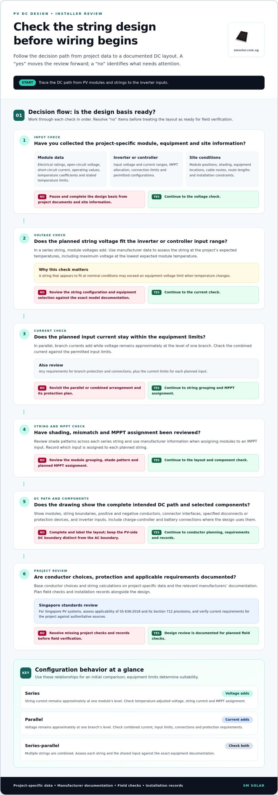
    • Trace the DC path from PV modules through disconnects and protection to the inverter inputs before selecting components.
    • Compare series, parallel and combined stringing by voltage, current and MPPT implications.
    • Use this solar panel wiring guide for installers to review module data, inverter limits, shading and cable routes in a consistent sequence.
    • Base string calculations and conductor choices on project-specific data and the relevant manufacturers’ documentation.
    • Plan field checks and installation records alongside the design, and verify applicable Singapore electrical, fire-safety and inspection requirements against authoritative sources.

    Solar Panel Wiring for Installers: What the Electrical Layout Must Connect

    PV wiring connects photovoltaic modules, strings, conductors and system equipment. A PV string is a group of modules connected electrically in series. The complete array is the collection of one or more strings feeding the system. A clear layout shows both how the modules form strings and how each string connects to the conversion equipment.

    Start at the modules and trace the DC path through string conductors and connectors, then through any specified disconnects or protection devices to the inverter inputs. The equipment order depends on the system design and applicable requirements. Show each device in its intended position rather than treating the path as a generic template. The Solar Panel Basics reference provides background on how modules generate electrical output; wiring design translates that output into compatible system connections.

    Which components belong in a solar panel wiring layout?

    Show the modules, string boundaries, positive and negative conductors, connector interfaces, protection devices and inverter inputs. If the design includes a charge controller and battery, include the controller’s PV-side terminals and the relevant battery-side connections. Label equipment clearly so the drawing can be checked against the components selected for installation.

    Keep the PV-side DC boundary distinct from the inverter-side AC boundary. The inverter converts DC power for the AC system, but this section covers only the DC wiring path and its connection to the inverter inputs, not AC installation procedures.

    What information should installers collect before designing?

    Build the design from project-specific documents and site information, not assumptions based on a familiar module or inverter. Record the applicable jurisdiction and project scope because electrical, fire-safety and inspection requirements can vary.

    • Module documentation: Record electrical ratings, open-circuit voltage, short-circuit current, operating values, temperature coefficients and stated temperature limits. Use the manufacturer’s data to assess how output may change across the project’s operating temperatures.
    • Inverter or controller documentation: Capture input voltage and current ranges, MPPT input allocation, connection limits and permitted configurations. Note which input is assigned to each planned string.
    • Site information: Map module positions, shading differences, equipment locations and cable routes. Record route length and installation constraints that could affect conductor planning.

    For Singapore projects, include SS 638:2018 and the PV provisions in Section 712 in the standards review, while confirming current applicability against authoritative requirements for the project. Check equipment limits against the documentation for the exact models selected. These inputs establish the design basis before string configuration, conductor sizing and field checks begin.

    How Series and Parallel Solar Panel Wiring Change Array Behaviour

    Configuration determines how module voltage and current reach each inverter or controller input. In series, module voltages add while string current remains approximately at the level of one module. In parallel, branch currents add while voltage remains approximately at the level of one branch. These relationships help with an initial comparison, but the equipment’s permitted input range and operating limits determine whether an arrangement is suitable.

    When is series wiring a suitable configuration?

    Series wiring connects modules positive-to-negative to form a string. Each module adds to the combined operating voltage, so check the string voltage against the inverter or controller input range. Also assess maximum voltage at the project’s lowest expected module temperature using manufacturer data. A string that fits at nominal conditions may exceed an equipment limit when temperature changes.

    Current through a series string is governed by its module design, rather than added across the modules. Shading or electrical mismatch can affect string output, depending on module characteristics and system design. Review shade patterns across the string and the manufacturer’s information before assigning modules to an MPPT input.

    When should parallel or series-parallel wiring be evaluated?

    Parallel branches combine current at a shared voltage. Compare the total input current with the inverter or controller’s permitted limits, and check any requirements for branch protection and connections. In a series-parallel arrangement, modules form multiple strings and those strings are combined. This offers another way to meet voltage and current needs, but assess each string and shared input against the exact equipment documentation.

    Series
    Electrical effect: Module voltages add; string current remains approximately at one module’s level.
    Design check: Confirm temperature-adjusted string voltage fits the input range, then verify string current and MPPT assignment.
    Typical trade-off: Higher voltage per string, with output potentially affected by shading or mismatch within that string.

    Parallel
    Electrical effect: Branch currents add; voltage remains approximately at one branch’s level.
    Design check: Confirm combined current, input limits and required protection for the arrangement.
    Typical trade-off: More current at the input and additional branch connections to plan.

    Series-parallel
    Electrical effect: Series strings are combined in parallel, increasing both array voltage and current relative to a single module.
    Design check: Verify each string’s voltage and current, total input limits and permitted MPPT configuration.
    Typical trade-off: More configuration flexibility, with more interaction between string design, protection and input allocation.

    Compare configurations against the actual modules, inverter or controller, site shading and cable routes. No arrangement is universally best. For project-specific DC component planning, solar panels, controllers and circuit protection can be considered as part of the same equipment set.

    Compare Solar Panel String Options Against Modules, MPPTs and Site Conditions

    A string configuration is viable only when it fits the module ratings, inverter or controller inputs, MPPT allocation and physical site layout together. Use a decision matrix to eliminate options that breach an equipment limit or cannot be routed practically. Screen configurations before detailed conductor selection so time is not spent sizing wiring for an arrangement the equipment cannot accept.

    Start with the exact module model and its technical documentation. The monocrystalline solar panels technical overview provides context on module data; final design values must still come from the relevant manufacturer documentation. General series and parallel principles explain electrical behaviour, but they do not confirm that different module models or string combinations are approved for a specific inverter.

    How do module and inverter limits narrow configuration choices?

    Compare module operating voltage and current, open-circuit voltage and short-circuit current with the inverter or controller’s input range and limits. Assess maximum string voltage at the relevant temperature conditions using the documented calculation method and manufacturer data. Then check the number and allocation of MPPT inputs, including any instructions for strings connected to a shared tracker.

    Rule out a configuration that exceeds an input voltage or current limit before selecting conductors. Similarly, a proposed string length outside the equipment’s permitted operating range cannot be made suitable by changing the cable. Keep manufacturer-approved module combinations distinct from general stringing principles.

    How do shading and cable routes affect the comparison?

    Map shade exposure by module location and planned string rather than treating the whole installation area as uniform. Where exposure differs, assess the effect on the proposed string grouping and MPPT assignment against the equipment documentation. Mark conductor routes, routing conditions and access constraints as well. A layout may be electrically compatible but still need revision if the route is impractical to install or inspect.

    Module limits: Confirm operating values and temperature-related voltage against manufacturer data. Reject string options that exceed documented limits.

    Inverter or controller inputs: Compare voltage and current ranges with the proposed configuration. Record the input limits that eliminate an option.

    MPPT assignment: Map each string to its intended tracker and follow the equipment’s configuration instructions.

    Shading: Note which modules and strings have differing exposure. Assess the effect before grouping them on an input.

    Route constraints: Mark cable paths, access and installation conditions. Carry these details into conductor design.

    For example, if a proposed string exceeds the documented maximum input voltage under the applicable temperature condition, remove it from consideration before comparing cable routes. Record the failed limit, data source and assumptions. This makes the decision reviewable and keeps the solar panel wiring guide for installers grounded in project evidence rather than a preferred configuration.

    Solar Panel Wiring: Design, Stringing and Field Checks

    A Solar Panel Wiring Workflow for String Sizing and Field Installation

    Use a controlled sequence from source data to as-built records. This solar panel wiring guide for installers links string selection, conductor specification and field verification, with calculations based on project inputs and applicable manufacturer documentation.

    1. Collect project documents. Gather module, inverter or controller datasheets, equipment instructions, site drawings and applicable project requirements. Record module electrical values, temperature-related limits, input ranges, MPPT allocation and installation conditions.
    2. Model candidate strings. Map proposed modules to strings and intended inputs. Include module locations and shading differences. Use the actual equipment models and the project’s documented operating conditions, not generic assumptions.
    3. Verify electrical limits. Check string voltage and current against inverter or controller limits, including temperature effects on voltage. Review permitted string and MPPT configurations in the equipment instructions. Remove options that fall outside a documented limit.
    4. Specify conductors and protection. Assess conductor ampacity and voltage drop using applicable design rules, route length and installation conditions. Select compatible connectors and protection components based on equipment documentation and project requirements. The solar circuit protection devices guide provides additional context for protection-device design.
    5. Install to the approved layout. Follow planned routes and support methods. Identify conductors and protect them from physical damage in accordance with the design and applicable requirements. Confirm connector compatibility and engagement using the connector manufacturer’s instructions. Avoid mixing connector types unless the manufacturers permit that combination.
    6. Inspect, test and record. Complete the checks and electrical tests required by the project procedure. Record the test method, instrument identification, results, date and responsible sign-offs. Update drawings to show installed string assignments, equipment inputs and approved field changes.

    How should installers verify string and conductor sizing?

    Keep calculations traceable. Show the source values, calculation method, temperature assumptions, route conditions and applicable design rules. Conductor ampacity depends on installation conditions, while voltage drop depends on the circuit and route. Avoid applying a universal cable size. Document the selected conductor against the specific installation and equipment requirements.

    Which field checks support a reliable wiring handover?

    Inspect routing, support, connector engagement, polarity identification and cable protection against the approved layout. Follow project procedures for electrical testing; a visual inspection does not replace required measurements. If a string connection or route changes in the field, record the change and verify the revised arrangement before handover.

    A complete record links the design to the installed system: datasheets, string calculations, equipment configuration, protection selection, inspection notes, test results and updated as-built drawings. For project-specific DC components, explore solar circuit protection and related hardware for your system design.

    Singapore Compliance, Project Records and Solar Wiring Component Planning

    Electrical design principles such as checking voltage, current, temperature effects and equipment compatibility apply broadly. Approval, inspection, fire-safety and installation rules depend on jurisdiction and project scope. Separate these two layers: document the engineering basis, then establish which Singapore requirements apply to the specific project.

    How should installers handle code and standards references?

    Do not apply US NEC references by default to Singapore projects. The identified Singapore electrical installation code of practice is SS 638:2018, including Section 712 for PV systems. Confirm the applicable edition, project requirements and approval processes against authoritative sources before work proceeds. Manufacturer instructions are equipment-specific requirements and should be distinguished from regulatory obligations.

    For fire-safety and lightning-protection considerations, establish which requirements apply to the project and verify them against relevant authorities and current standards documents. SS 555:2018 is the identified lightning protection standard. Requirements and review responsibilities may depend on system scope, so do not treat a general reference as a complete approval checklist.

    How can component planning support a traceable design?

    Translate each design requirement into a component category and specification reference. Match module data to the selected inverter or charge controller inputs; include batteries where the system design requires them; and document protection-device selection against the circuit design and applicable equipment instructions. Record the manufacturer, model and relevant datasheet revision so procurement can be checked against the approved design.

    • Equipment records: Keep module, inverter, controller and battery documentation with the design file.
    • Protection records: Link each selected protection device to its intended circuit and design basis.
    • Drawing control: Maintain the wiring schedule, single-line diagram and revision history together.
    • Handover evidence: File inspection and test records against the installed configuration, including approved changes.

    This traceability reduces ambiguity between the design, purchased hardware and installed arrangement. If a component changes, review the affected calculations, input compatibility and drawings rather than updating the procurement list alone.

    SM Solar supplies wholesale solar hardware, including monocrystalline solar panels, charge controllers, batteries and solar circuit protection. Its system integration capabilities support the assembly of project-specific DC component sets, alongside the project’s engineering and regulatory review. Keep procurement aligned with approved specifications; the solar energy equipment supplier buyer’s guide provides further context for organizing that process.

    Close the project file with applicable standards references, approval records, the final equipment schedule, test evidence and as-built drawings. Verify current Singapore electrical, fire-safety and inspection requirements through authoritative sources for each project. This keeps the compliance basis clear and makes later review more reliable.

    Put the Wiring Plan to Work

    Make the next project easier to review by turning the design basis into a reusable project checklist. Set out the required source documents, calculation references, equipment selections, inspection points and handover records in one controlled package. Update it for each site and equipment combination instead of carrying assumptions forward. This helps keep design decisions visible from initial specification through field verification.

    Use this solar panel wiring guide for installers as a reference when building a project-specific component schedule. Match each selected item to the approved design and manufacturer documentation, then keep procurement records aligned with the final wiring plan.

    Review SM Solar’s solar hardware range to plan components for your next PV project. A clear design basis and well-organised equipment schedule give your team a practical starting point for the work ahead.

    Frequently Asked Questions

    How do installers calculate the maximum number of solar panels in a string?

    Use the module’s open-circuit voltage, adjusted for the lowest design temperature, to calculate the maximum series count allowed by the inverter’s maximum DC input voltage. Then check that the resulting operating voltage also fits the inverter’s MPPT range. Apply the manufacturer’s calculation method and temperature data. This gives an equipment-based upper limit, not a recommended string length; current limits and project requirements may reduce it further.

    What happens if a PV string exceeds the inverter’s maximum input voltage?

    An overvoltage string can cause the inverter to trip or fail to operate, and may damage its input circuitry. The actual response depends on the equipment, but built-in protection should not be treated as permission to exceed a stated limit. Recheck the string calculation using the module’s temperature-adjusted open-circuit voltage and the inverter documentation. Do not connect the string until the design is within the specified maximum.

    Can solar panels with different electrical ratings be connected in the same string?

    Only if the equipment manufacturers’ instructions and the project design permit that combination. In a series string, current is shared, so modules with different current characteristics can constrain the string’s operating behaviour. Differences in voltage can also affect the usable operating range. Compare the exact module datasheets, not just nominal wattage, and document the basis for mixing models. If compatibility cannot be established, keep the modules in separate, appropriately assigned strings.

    Are MC4-compatible connectors from different manufacturers interchangeable?

    No. A connector described as MC4-compatible is not automatically approved for mating with every connector using that interface. Differences in construction or contact design can affect connection quality and safety. Use connector combinations that the respective manufacturers explicitly permit, and follow their assembly instructions and tooling requirements. Record connector make and model in the installation schedule so replacements or field changes do not introduce unverified pairings.

    How should installers assess voltage drop in solar panel wiring?

    Calculate voltage drop using the circuit current, conductor material and cross-sectional area, operating temperature, and the full current path length. For a DC circuit, account for both outgoing and return conductors. Compare the calculated drop with the project’s design criteria and applicable requirements, then adjust conductor selection or routing if needed. Keep the calculation inputs and method on file; a cable size alone does not demonstrate acceptable voltage drop.

    What records should be included in a solar installation wiring handover?

    Include the final wiring diagram and string schedule, equipment datasheets, string and conductor calculations, protection-device selections, inspection notes, test methods and results, instrument details, sign-offs, and a revision history. Add approved field changes and identify the final equipment models and MPPT assignments. A complete handover lets a reviewer trace each installed connection back to its design basis and helps future maintenance teams understand what was built.

    Does the NEC apply to solar panel wiring projects in Singapore?

    The NEC is a US electrical code and should not be assumed to govern a Singapore project. Identify the Singapore requirements and approval processes applicable to the project scope; SS 638:2018, including Section 712 for PV systems, is the relevant electrical installation standard identified for Singapore. Confirm current requirements and editions with authoritative sources before design or publication. Manufacturer instructions remain essential for equipment-specific limits, but they are not a substitute for local requirements.

  • Off-Grid Solar Battery Storage: A System Design Guide

    Off-Grid Solar Battery Storage: A System Design Guide

    What if the battery with the highest capacity still can’t keep an off-grid system reliable? Battery sizing depends on the loads it must serve, the energy solar panels can generate, conversion losses and periods without adequate sunlight. That’s why off-grid solar battery storage needs to be designed as part of the complete system, not selected in isolation.

    It’s reasonable to start with storage: the battery determines how much energy is available when generation falls short. But rated capacity alone doesn’t show how much energy is usable or whether the battery can work properly with the inverter and charge controller. A mismatch can limit the performance of the whole system.

    This guide explains how to relate project loads to usable battery capacity, compare storage options using relevant technical criteria, and assess the hardware required beyond the battery. It also maps the roles of solar panels, charge controllers, hybrid inverters and circuit protection in an integrated design. From water monitoring to CCTV applications, a methodical workflow helps project teams specify a system around its operating requirements.

    Key Takeaways

    • Design off-grid solar battery storage around project loads and energy requirements, not a preferred battery size.
    • Distinguish nominal capacity from usable capacity when comparing battery options.
    • Assess operating conditions, lifecycle data and electrical compatibility alongside capacity.
    • Separate critical loads from deferrable loads before estimating storage requirements.
    • Consider the complete hardware path, including solar panels, charge controllers, hybrid inverters and circuit protection.

    What Off-Grid Solar Battery Storage Does, and Where Its Limits Begin

    Off-grid solar battery storage is one component in an electrical system designed to supply energy independently of a utility connection. Solar panels generate electricity, the battery stores some of that energy for later use, and power-conversion equipment delivers electricity in a form suitable for connected loads. The battery shifts energy across time; it doesn’t generate energy or define the system on its own.

    Definition: Off-grid battery storage is the usable electrical energy held for later delivery within a system designed to operate without relying on a utility supply.

    This distinction matters. A battery’s capacity alone can’t establish whether a project will meet its energy needs. The answer depends on the loads, when they operate, how much generation is available, and how much of the battery’s rated energy can be used within its operating limits. A general overview of home energy storage systems provides broader context on storage’s role, but project design still requires inputs specific to the system.

    Off-grid operation versus grid-connected backup

    An off-grid system is designed to supply its loads without depending on a utility connection. A grid-connected backup system, by contrast, normally operates alongside a utility supply and uses stored energy to serve selected loads when that supply is interrupted. Hybrid equipment can support different operating arrangements, but the project’s intended mode must be clear in the design.

    The objective changes the storage specification. A continuously independent supply must be assessed against the loads and generation available throughout expected operating conditions. Backup design centres on the loads that must remain powered during an interruption and the required backup period. These are different design cases, so a battery selected for one shouldn’t automatically be assumed suitable for the other; for instance, providers such as Bright Earth Solar configure dedicated battery storage systems tailored specifically to whether a property needs standalone power or seamless backup during an outage.

    What determines practical system autonomy?

    Autonomy describes how long a system can support its defined loads under specified conditions. It depends on three connected inputs:

    • Load profile: Which equipment operates, its energy demand, and the timing and duration of use.
    • Available generation: The solar energy the array can supply under the project’s operating conditions.
    • Usable stored energy: The portion of battery capacity available to serve loads, accounting for the battery’s operating limits and system conversion.

    Consider a remote monitoring installation. Its design starts with the equipment that must remain active and its operating schedule, not an assumed battery size. If generation falls below consumption over time, stored energy will be drawn down. A larger battery can provide a temporary reserve, but it can’t compensate indefinitely for inadequate generation. Load reduction, additional generation, or a different operating objective may need to be considered.

    There is no single autonomy figure that suits every project. Calculate requirements from the documented load profile, expected generation and usable battery energy, then assess how those inputs interact under the conditions the system is designed to handle. This project-specific basis prevents nominal battery capacity from being mistaken for guaranteed operating time.

    How Off-Grid Solar Battery Storage Fits Into the System

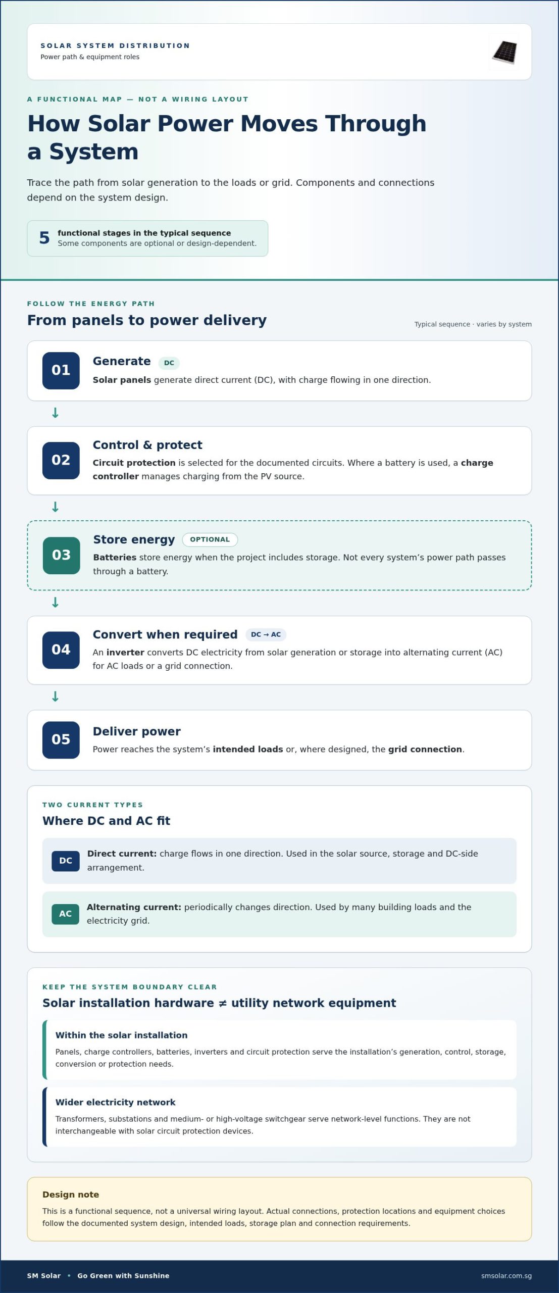
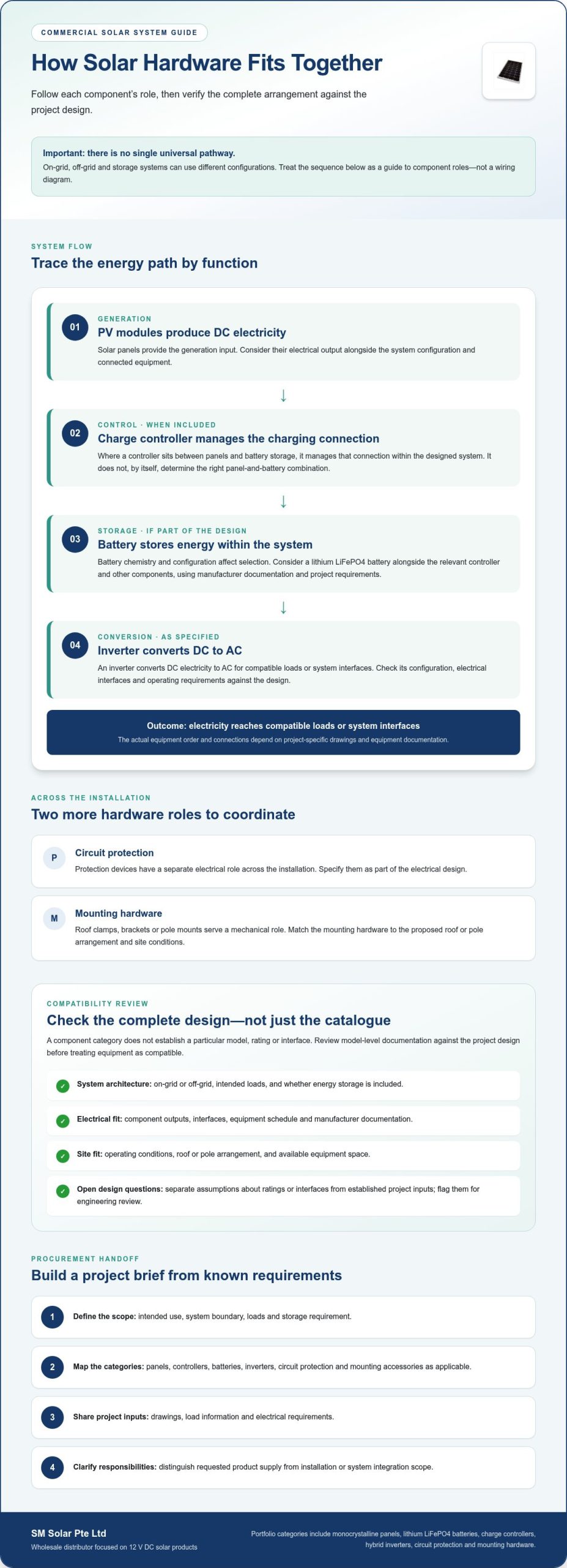
    Off-grid solar battery storage operates within a connected electrical architecture. Energy flows from photovoltaic (PV) modules to a charge controller, then into the battery. From there, power may supply compatible DC loads or pass through an inverter to serve AC loads. Circuit protection and correctly selected wiring support safe, coordinated connections throughout the system.

    Generation produces energy, control regulates charging, storage shifts energy availability, and conversion supplies the form of power required by the loads. Each function depends on the surrounding components. Storage helps manage the variability of solar generation, but the project’s electrical design determines how each component is configured and how they operate together.

    From solar panels to stored energy

    Solar panels produce direct-current (DC) electricity. A charge controller sits between the PV array and battery, managing the charging process in line with the connected equipment’s electrical requirements. This stage isn’t simply a cable connection: the array and controller must be configured for the battery system they serve.

    Many controllers use maximum power point tracking (MPPT). MPPT adjusts the array’s operating point to make use of available PV power as conditions vary. Its role is to manage the PV-to-battery charging interface, not to increase the energy the panels can generate beyond available sunlight.

    From battery output to usable electrical loads

    The battery stores DC energy. If the project includes AC equipment, an inverter converts DC power into AC output suitable for those loads. Its electrical input must suit the battery system, while its output must align with the connected equipment’s requirements. DC loads may follow a different path, so the load inventory affects the architecture.

    Circuit protection belongs in the design from the outset. Protection devices are placed on relevant circuits to help manage electrical faults and protect connected conductors and equipment. Their selection and placement depend on the circuit, components and system configuration; they aren’t interchangeable accessories to add after sizing is complete.

    Review the whole path, not just adjacent components. Confirm that the PV array configuration suits the controller, that controller and battery requirements align, and that the inverter suits both the DC source and intended AC loads. Wiring, connection methods and protection-device ratings also require technical review for the project. A mismatch at any interface can constrain the system even when individual components appear suitable.

    For projects such as monitoring installations, this component view helps translate load requirements into a coordinated hardware specification. SM Solar supplies solar system hardware, including panels, charge controllers, batteries, hybrid inverters and circuit protection, supporting designs that account for generation, storage, control and conversion together.

    How to Compare Off-Grid Battery Storage Options

    Compare batteries against the project’s operating requirements, not a headline capacity or chemistry label. For off-grid solar battery storage, the useful comparison is whether a battery can deliver the required energy under the project’s conditions and work with the charge controller and inverter. SM Solar supplies lithium LiFePO4 batteries. Assess other battery categories using current, product-specific manufacturer documentation rather than assumptions about an entire chemistry.

    Use a consistent comparison framework. Record each specification, the conditions under which it applies and any limits that affect the project.

    Comparison factor What to examine
    Usable capacity Nominal capacity, manufacturer-stated usable energy and any stated discharge limits.
    Operating conditions Manufacturer limits for charging and discharging, including the conditions under which published figures apply.
    Lifecycle data Cycle-life or retention claims, with the test conditions and definitions shown alongside them.
    System compatibility Battery voltage and charging requirements against the controller, inverter and system configuration.

    Compare battery chemistry against the application

    LiFePO4 is an option in SM Solar’s battery range, but chemistry alone doesn’t determine suitability. Start with the application: identify the required energy, operating pattern and equipment interface, then compare product documentation against those requirements. If considering other chemistries, use the same criteria and avoid generalising performance from one model to every battery in that category.

    Manufacturer operating conditions are essential context. A cycle-life statement, for example, is meaningful only with its stated test conditions and definition. Compare like with like. If two specifications use different conditions, their figures aren’t directly equivalent. Record the source document and conditions with each entry so the selection remains traceable.

    Nominal capacity, usable capacity and operating limits

    Nominal capacity is the battery’s stated rated capacity. Usable capacity is the energy available for the application within specified operating limits. These are related, but they’re not interchangeable. The manufacturer’s documentation establishes how capacity is defined and the conditions under which it applies.

    Depth of discharge (DoD) describes how much of a battery’s capacity has been discharged. A stated DoD limit affects the amount of energy available for use, so compare usable capacity rather than treating the full nominal rating as available. Don’t infer a universal usable fraction: the applicable limit depends on the product documentation and system configuration.

    For a practical selection, match each candidate’s usable energy and operating limits to the project’s load requirements, then check compatibility with the charging and conversion equipment. Treat lifespan and retention as product-specific claims, not fixed chemistry-wide promises. This keeps the comparison grounded in verifiable specifications and relevant to the actual system.

    Off-Grid Solar Battery Storage: A System Design Guide

    How to Size Off-Grid Solar Battery Storage for a Project

    Specify storage only after the project’s loads and generation have been assessed. Battery selection comes later. This sequence makes the design traceable to actual operating requirements, whether the system serves monitoring equipment, CCTV or water-related loads.

    Storage sizing must follow the load and generation assessment, not precede it.

    1. Inventory the loads. List each device, its electrical demand and operating schedule. Use metered consumption or project records where available. Mark which values are measured and which are estimates, and record the source of each estimate.
    2. Classify load priority. Separate critical equipment from deferrable loads. For a monitoring project, continuous sensing or communications may be critical, while a non-essential load could be scheduled for periods of stronger generation or excluded during constrained operation. The project owner defines these priorities.
    3. Establish the operating requirement. Define when loads must run and the autonomy objective: how long the system should support the selected loads without sufficient solar input. Avoid assuming every load runs continuously or that every project requires the same autonomy period.
    4. Assess generation over the operating period. Use project-specific solar generation information and account for periods when generation may be reduced. Compare the energy expected from the array with load demand over the same period, rather than relying on an average that hides low-generation intervals.
    5. Translate the assessment into storage needs. Estimate the energy required during periods when generation cannot meet demand, then relate that requirement to the battery’s manufacturer-stated usable capacity and operating limits. The result is a design requirement, not a guarantee of supply under every condition.

    Build a project load profile

    Make the load record detailed enough to show timing, not just total consumption. For each device, note operating hours, duty cycle, startup or intermittent use where relevant, and whether its demand is measured or estimated. Identify critical monitoring, CCTV, water-quality or water-monitoring equipment when it applies to the project. This profile provides the basis for prioritisation and makes assumptions visible for later review.

    Translate demand into a storage specification

    Compare the required stored energy with usable battery capacity, not nominal capacity alone. Then cross-check the candidate battery against expected solar generation, charge-controller requirements and inverter input and output needs. Review how the design responds to low-generation periods and document any backup strategy or load-shedding approach. Neither storage capacity nor a backup plan should be treated as a promise of uninterrupted operation.

    For a coordinated specification, align the load assessment with the panels, batteries, charge controllers, hybrid inverters and circuit protection in the design. Explore off-grid system integration with SM Solar when developing the project’s hardware requirements.

    Specify Off-Grid Solar Battery Storage With SM Solar

    Once the load profile, autonomy objective and generation assessment are established, translate them into a coordinated hardware specification. SM Solar supplies off-grid system components wholesale and provides system integration, installation and after-sales maintenance. The battery is one part of that package. Its requirements need to align with the solar array, charge control, power conversion and circuit protection.

    Coordinate the hardware package around the design

    Use the project design as the basis for component selection. Match the battery’s usable capacity and charging requirements to the load profile and expected energy supply. Then align the charge controller with the PV array and battery, and the hybrid inverter with the battery and required loads. Specify circuit protection for the relevant system circuits rather than treating it as an accessory chosen after the other equipment.

    SM Solar supplies lithium LiFePO4 batteries, monocrystalline solar panels, solar charge controllers, hybrid inverters and solar circuit protection. Tie each component to a defined requirement, using manufacturer documentation to assess electrical compatibility. This keeps the specification coherent across the energy path instead of comparing parts in isolation.

    For battery chemistry and protection considerations, consult SM Solar’s lithium battery and solar circuit protection information as part of the component review. The final selection should reflect the project’s electrical design and the specifications of the equipment being integrated.

    Apply the approach to off-grid project requirements

    Off-grid applications differ by load and operating schedule. SM Solar’s documented project examples include water-quality and water-monitoring applications, CCTV and noise monitoring. Each requires its own assessment of which equipment must operate, when it runs and how the system should respond when solar generation is limited. The application informs the design; it doesn’t establish a standard battery size or guarantee a particular operating outcome.

    System integration and installation bring the specified hardware together within the project architecture. SM Solar also provides after-sales maintenance. In each case, the important design link is between project requirements and selected equipment: battery capacity and limits, panel generation, controller charging requirements, inverter output needs and protection-device selection. This component-level coordination is central to specifying off-grid solar battery storage for an actual application.

    To move from design criteria to component selection, review SM Solar’s off-grid solar hardware and prepare the project load profile, generation assumptions and equipment requirements for the specification process.

    Turn the Design Basis Into a Coordinated Specification

    Turn the design basis into a procurement-ready brief. Record approved load priorities, operating schedules, autonomy objectives, generation assumptions, usable-energy requirements and electrical interfaces. Keep measured values distinct from estimates, and note any assumptions that still need resolution. This gives the project team a consistent basis for reviewing component choices and evaluating substitutions against the requirements.

    That discipline applies across off-grid solar battery storage projects, including water-quality, water-monitoring and CCTV applications. SM Solar supplies batteries, charge controllers, solar panels, hybrid inverters and circuit protection devices. Its capabilities also include system integration, installation and after-sales maintenance, linking hardware supply with the broader project workflow without treating a battery as a complete system.

    Use the brief to review the relevant equipment as a coordinated set, with each selection tied to a defined project requirement. Review SM Solar’s off-grid solar hardware range and use your project brief as the basis for a clear, project-specific specification.

    Frequently Asked Questions

    Can an off-grid solar battery system be expanded after installation?

    Yes, if the existing equipment and system design support additional battery capacity. Expansion can be constrained by the inverter, charge controller, battery management system, wiring, protection devices and the manufacturer’s rules for connecting battery units. Before adding storage, review the installed equipment’s specifications and condition, then recalculate the system requirements. A compatible expansion may still require changes to settings or other components.

    How does a battery management system support battery operation?

    A battery management system (BMS) monitors battery operating parameters and manages functions defined by the battery manufacturer. Depending on the design, it may monitor cell voltage and temperature, control charging or discharging, and trigger protective limits. It doesn’t increase the battery’s rated capacity or replace correct system design. The battery documentation should specify how its BMS communicates or coordinates with the inverter and charging equipment, if applicable.

    What happens to an off-grid battery when it reaches its discharge limit?

    At its specified discharge limit, battery controls may restrict or stop further discharge to protect the battery. The effect on connected equipment depends on the system: loads may lose supply, or an inverter may shut down or signal a fault. The system must then recharge the battery before normal operation resumes. For off-grid solar battery storage, understand the configured cut-off and recovery behaviour from the battery and inverter documentation.

    Can an off-grid solar system use a generator as backup?

    Yes, a generator can be included in some off-grid designs, provided the inverter or charging arrangement supports it and the equipment is configured for the generator’s electrical output. The design must account for connection, switching, charging control, protection and safe operation. A generator doesn’t remove the need to size storage around the loads. Its role and operating procedure should be defined in the system plan.

    How should battery storage be maintained in an off-grid system?

    Follow the battery and equipment manufacturers’ maintenance instructions. Keep records of system alarms, operating conditions and any changes in observed performance, and inspect the installation for visible damage, corrosion or loose connections only where safe to do so. Don’t open sealed battery enclosures or alter electrical connections without appropriate technical competence. Maintenance intervals and permissible inspection procedures depend on the specific battery and system configuration.

    Are off-grid solar batteries recyclable at end of life?

    Many battery materials can be recovered through suitable recycling processes, but the correct route depends on the battery chemistry and local collection arrangements. Don’t place a spent battery in general waste or dismantle it. Keep it intact and follow the applicable battery collection or recycling instructions for your location. If a battery is damaged, handle it according to the manufacturer’s safety guidance and the relevant local disposal process.

    Can different battery types be connected in the same system?

    Only when the system and battery manufacturers explicitly allow the proposed combination. Different chemistries, models, ages or capacities can have different voltage characteristics, charging requirements and operating limits. Combining them without an approved design may cause uneven charging or operation outside specified conditions. Check the permitted configuration for the batteries, BMS, charge controller and inverter before making changes. Don’t assume batteries with similar nominal voltage are compatible.

  • Monocrystalline PV Modules: 2026 Procurement Guide

    Monocrystalline PV Modules: 2026 Procurement Guide

    Choosing a monocrystalline PV modules supplier involves more than comparing names. The right fit depends on whether the proposed modules match the project design, whether their technical documentation is clear and comparable, and whether the supply scope includes the required hardware. A directory can help identify potential sources, but it cannot show whether a supplier’s products and capabilities fit a specific procurement requirement.

    Module specifications can be difficult to compare when ratings, dimensions and supporting documents use different formats. For projects in Singapore, a consistent evaluation framework helps buyers check the details against project requirements and identify gaps before procurement.

    This guide explains how to assess supplier fit, compare module documentation and define the wider solar hardware scope. It also outlines how SM Solar’s wholesale supply of monocrystalline solar panels and related hardware, alongside its system integration, installation and after-sales maintenance capabilities, can fit into a project review. Use it to make a supply decision based on documented requirements, not directory presence alone.

    Key Takeaways

    • Define the project application, system architecture and procurement scope before comparing module offers.
    • Assess a monocrystalline PV modules supplier by documented project fit, supply scope and support capabilities, not directory presence alone.
    • Use a consistent comparison table to review module specifications and technical documents, keeping verified facts separate from assumptions.
    • Make procurement decisions traceable by recording requirements, open questions and document revisions at each review stage.
    • Assess how SM Solar’s wholesale supply and documented integration, installation and after-sales capabilities relate to your project requirements.

    Why monocrystalline PV modules supplier selection affects project procurement

    A module listing identifies a product category, but not whether the supply arrangement fits your project. Establish who manufactures the modules, who supplies them and who is responsible for system integration. These roles affect how specifications are reviewed, what is included in a purchase and how procurement connects with project delivery.

    A monocrystalline PV modules supplier provides photovoltaic modules against a defined project requirement; a module manufacturer produces the cells or assembles the modules. The supplier may be the manufacturer or a separate wholesale distributor. The distinction matters: a manufacturer’s technical information describes its product, while a distributor’s offer addresses procurement and supply. Neither role alone establishes that engineering, installation or maintenance is included.

    What does a monocrystalline PV modules supplier provide?

    A manufacturer produces photovoltaic cells and modules. A wholesale distributor sources products and supplies them for project procurement, helping buyers match the purchase to the stated requirement and scope. A system integrator has a different role, coordinating components and system design. A business may have more than one capability, but assess each role separately rather than assuming it is part of every supply offer.

    Separating these roles clarifies accountability. The technical review can focus on product documents and their match to the project brief. The commercial review can cover the supply scope and purchasing coordination. Any integration or installation work should be treated as a distinct capability. SM Solar wholesales monocrystalline solar panels and has system integration, installation and after-sales maintenance capabilities for end users.

    Which project buyers typically source modules wholesale?

    Wholesale sourcing is relevant to EPCs, installers, project developers and organisations procuring solar system hardware. Their requirements may include a defined module quantity, design-aligned product information, a clear supply scope and coordination with the wider procurement plan. The appropriate review depends on the project brief, so a directory entry or manufacturer name alone cannot establish fit.

    Residential consumers seeking installation have different needs from professional buyers purchasing modules for a project. This guide focuses on supplier and procurement assessment, not household installation enquiries. For background on cell structure and module fundamentals, see Monocrystalline Solar Panels Singapore: Technical Overview 2026. For a broader explanation of the technology and its photovoltaic use, see Monocrystalline silicon in photovoltaics.

    Supplier selection also affects the order of project decisions. If product information does not map clearly to the design requirement, technical review can stall while inconsistencies are resolved. If the commercial scope is unclear, purchasing coordination can become detached from the project plan. A practical shortlist records the supplier’s role, the evidence supporting product fit and the boundaries of the offer. This gives procurement, engineering and project teams a shared basis for review before they commit.

    Which monocrystalline PV module requirements should buyers define first?

    Start with the project brief, not a supplier catalogue. Record the application, system architecture, intended operating conditions and procurement scope before comparing modules. A ground-mounted project and a roof-mounted project, for example, may have different physical constraints and mounting interfaces. Describe the actual design requirements rather than assuming a module will suit the project simply because it is monocrystalline.

    Module suitability depends on documented project requirements and evidence that the proposed module matches them. No universal set of thresholds replaces design review. To assess suppliers consistently, compare each candidate against the same project-specific fields.

    Which module specifications belong in the procurement brief?

    Use the project design documents to set the required parameters. Capture the expected module power, voltage and current values, physical dimensions and connector details. Include any project-specific operating conditions or interface constraints that affect selection. These fields define the project’s needs; the manufacturer’s datasheet provides the model-specific values to review.

    • Electrical: Power, voltage and current values stated in the design and datasheet.
    • Physical: Module dimensions and any relevant space or mounting constraints.
    • Connection: Connector details and interface requirements specified for the system.
    • Scope: The module quantity and procurement boundaries defined by the project.

    Keep units and document references consistent across supplier submissions. If a field is missing, unclear or inconsistent between documents, log it as an open item. Don’t fill gaps with assumptions or values from a different module model. Resolve discrepancies before shortlisting so the technical comparison reflects the product actually proposed.

    How should buyers assess documentation and compatibility?

    Review each datasheet and relevant declaration against the design documents. Match the exact module model and document revision to the proposed supply. Then compare its electrical and physical interfaces with the system architecture, including inverter input requirements and the mounting design. Establish compatibility using project documents and component requirements, not a product category or a similar-looking specification.

    Use one comparison template for every candidate. Record each stated value, its source document and revision, the project requirement and any unresolved variance. This makes missing information visible and gives engineering and procurement teams a shared review trail. Don’t rank offers by one headline figure while overlooking dimensions, connectors or other design interfaces.

    For more background on module fundamentals, consult Monocrystalline Solar Panels Singapore: Technical Overview 2026. Once the project fields are defined, include SM Solar’s wholesale monocrystalline solar panel supply in your procurement review.

    How to compare monocrystalline PV modules suppliers objectively

    A fair supplier comparison is evidence-based and specific to the project. Use the same evaluation framework for every candidate and record the source for each finding. This helps distinguish documented capabilities from assumptions, directory descriptions and sales language. A manufacturer’s scale or presence in a supplier directory may inform initial research, but neither proves that its modules or supply scope fit a particular project.

    For each supplier, compare the same categories against the project brief. Keep technical suitability separate from purchasing scope and support capabilities. A strong result in one category should not conceal missing evidence in another.

    What evidence should a supplier comparison include?

    Build a record that links each claim to its evidence. Note the product model, datasheet source and revision, then capture the declared specifications relevant to the project. Record procurement, integration and after-sales activities separately, identifying what falls within the stated scope. Mark unavailable, inconsistent or unverified information as unresolved. Don’t treat an assumption or promotional phrase as an established fact.

    • Product documentation: Model identification, datasheet, declared specifications, source and revision.
    • Project fit: Evidence that the documented product aligns with the project’s stated requirements.
    • Supply scope: The products and procurement activities included in the offer.
    • Support scope: Stated integration or after-sales capabilities, recorded separately from product supply.
    • Open items: Missing documents, conflicting values and claims that still need evidence.

    How do distributors and manufacturers differ in a sourcing decision?

    A manufacturer produces cells or modules and provides product information for its own products. A wholesale distributor sources and supplies products for procurement. A system integrator coordinates system components or design activities. These roles can overlap, but don’t assume a distributor manufactures modules or a manufacturer provides installation. Identify the responsibility relevant to your project and record who is accountable for each part of the proposed scope.

    For example, a manufacturer’s datasheet can support technical review, while a distributor’s proposal can define the procurement supply. If the project requires coordination or integration, assess that capability as a separate line item. For wider context on supplier assessment and hardware scope, see Solar Energy Equipment Supplier: A Buyer’s Guide for 2026.

    Use the comparison to create a shortlist that reflects project needs, not a score detached from them. Prioritise unresolved technical or scope questions before purchase coordination, and retain document revisions with the evaluation record. This gives procurement and engineering teams a common basis for decisions. Include SM Solar’s wholesale monocrystalline solar panel supply in the same project-specific review.

    Monocrystalline PV Modules: 2026 Procurement Guide

    How to prepare a monocrystalline PV module procurement workflow

    A defined workflow takes a module purchase from project need to a reviewable procurement decision. It also prevents assumptions about quantities, delivery dates or commercial terms from being treated as confirmed information. Assign someone to maintain the record and keep one controlled set of project requirements, supplier responses and document revisions.

    1. Prepare the project brief. State the application, system architecture, operating conditions and procurement boundaries. Identify the design documents that establish module requirements.
    2. Prepare the request for quotation. Specify the required electrical and physical parameters, supporting documents and any project-defined quantity or delivery requirement.
    3. Review technical responses. Compare every offer against the same requirements. Record deviations, missing evidence and questions that need technical resolution.
    4. Align the scope. Separate module supply from related hardware, integration and other responsibilities. Document the purchasing scope before coordination proceeds.
    5. Maintain the decision record. Store selected document revisions, assumptions, open items and purchasing decisions together for traceability.

    What should a module request for quotation contain?

    A useful RFQ gives each monocrystalline PV modules supplier the same basis for responding. Include the project application, module specifications drawn from the design documents and the supporting product documents needed for review. State quantities and delivery requirements once the project team has established them. List related hardware separately so it does not blur the module specification or create ambiguity about what is being quoted.

    Keep the request precise, while distinguishing fixed requirements from information still under development. For example, mark a pending quantity as unresolved rather than inserting an estimate as if it were approved. Record the RFQ version and issue date, and compare responses against that same version. This provides a clear reference if project requirements change.

    How should project teams review supplier responses?

    Review responses against the same specification fields and scope categories used in the RFQ. Match each stated module value to its supporting document and note the model and revision. Log deviations for technical review instead of treating them as accepted substitutions. Keep unverified claims and unresolved assumptions visible in the decision record.

    Then check procurement boundaries. Identify which items are included, which activities are assigned to the supplier and whether integration responsibilities are stated separately from module supply. Record delivery details and commercial terms as presented for the specific project. Don’t assume they apply to another order or remain unchanged.

    Once requirements and review records are organised, use them to guide purchasing coordination for the selected scope. To review SM Solar’s solar panel range in the context of a project brief, visit Review SM Solar’s solar panel range.

    How SM Solar supports monocrystalline PV module supply

    SM Solar is a wholesale distributor of solar products, including monocrystalline solar panels and related solar hardware. For procurement teams, the company is a supply-chain source for project requirements, with capabilities that include system integration, installation and after-sales maintenance for end users. Assess these as distinct parts of the scope: wholesale supply can be reviewed separately from any integration or service requirements relevant to the project.

    SM Solar was established in 2008 and became a private limited company in 2016. This business history provides context when assessing a monocrystalline PV modules supplier. The more direct procurement questions remain product documentation, project fit and a clearly defined supply scope.

    What is SM Solar’s role in solar hardware supply?

    SM Solar’s wholesale distribution supports buyers procuring solar hardware against project requirements. Its product categories include solar panels, solar charge controllers, batteries and solar circuit protection devices. Identify the required products in the project brief, then assess the relevant product documentation and supply needs as part of procurement. Base decisions on project-specific product records for details such as module brand, rating, certification, stock and delivery terms.

    System integration, installation and after-sales maintenance are capabilities for end users. Consider them separately from wholesale module supply and include them in project planning where relevant. This distinction clarifies responsibilities for procurement and technical teams, particularly when the required scope includes hardware alongside other project work.

    How does documented project experience support procurement confidence?

    SM Solar’s company profile lists 10 off-grid and 5 on-grid customer organisations. These figures provide context about the organisation’s documented customer portfolio. They are not product endorsements or evidence that a particular module will suit a new project. Base selection on the project design, current module documentation and the proposed scope for your procurement.

    Project context is most useful when considered alongside defined responsibilities. The listed off-grid and on-grid organisations show customer activity in both project contexts, while the documented integration and after-sales capabilities provide further information about scope. These details can inform procurement review, but they do not replace technical verification or establish project outcomes.

    A practical evaluation keeps the evidence distinct: company background, product documentation, supply scope and capabilities each answer different questions. This lets project teams assess SM Solar as a wholesale solar supply partner while retaining project-specific criteria for module selection and procurement coordination.

    Explore SM Solar’s solar product range as you define the supply scope for your project.

    Move from supplier review to a controlled procurement decision

    Before releasing a purchase order, use the approved project requirements as the procurement baseline. Keep the selected module documentation, agreed supply scope and resolved technical deviations together in the project record. This gives the team a clear reference if specifications change or purchasing coordination passes between departments.

    Assess a suitable monocrystalline PV modules supplier against that baseline, including product supply and any relevant integration or after-sales requirements within their defined scope. SM Solar’s wholesale distribution of monocrystalline solar panels and its system integration, installation and after-sales maintenance capabilities can inform that project-specific review.

    Use the same requirements to assess the solar hardware needed for the project, and keep unapproved substitutions out of the purchasing record. A disciplined handover helps keep procurement decisions traceable from selection through order coordination.

    Explore SM Solar’s solar product range to plan your project procurement. Start with a clear brief and documented review, then align the supply scope with your requirements.

    Frequently Asked Questions

    What is the difference between a monocrystalline PV module supplier and a manufacturer?

    A manufacturer produces photovoltaic cells or assembles modules, while a monocrystalline PV modules supplier provides modules for a buyer’s project. The supplier may be the manufacturer or a separate distributor. For procurement, identify which organisation issued the product documentation and which party is responsible for the supply offer. This keeps technical product claims distinct from purchasing and coordination responsibilities.

    What documents should I request from a monocrystalline PV modules supplier?

    Request the datasheet for the specific module model, along with applicable product declarations, installation instructions and warranty documentation. Check that model identifiers and revision details are visible so the documents can be matched to the quoted product. If a document refers to a different model or leaves a requirement unclear, record the discrepancy for review instead of relying on a general catalogue description.

    Can monocrystalline PV modules work with different inverter types?

    They can be used in systems with different inverter types when the module’s electrical characteristics and array configuration meet the inverter’s requirements. Compare the module voltage and current information with the inverter’s input limits and the planned string arrangement. The inverter label alone does not establish compatibility. A system designer should assess the specific module and inverter documents together before selecting the components.

    How do I check whether a PV module specification suits my project?

    Compare the exact module model’s datasheet with the project design and installation constraints. For example, confirm that its documented dimensions fit the allocated mounting area and its electrical values align with the planned system configuration. Check connector and mounting interfaces as well. Keep the source document and revision with the review, and refer any mismatch to the project’s technical reviewer before purchase.

    Are monocrystalline PV modules suitable for off-grid systems?

    Yes, monocrystalline PV modules can be used in off-grid systems when the array is designed around the site’s energy requirements and the selected charge-control, inverter and battery configuration. Module choice alone does not determine off-grid suitability. The system design must account for how the components work together and the intended operating conditions. Review project-specific documentation for the complete system rather than selecting modules in isolation.

    Does SM Solar provide installation and after-sales maintenance?

    Yes. SM Solar’s capabilities include installation, after-sales maintenance for end users and system integration. These are distinct from its wholesale distribution of solar products, including monocrystalline solar panels. For project planning, define the required scope clearly so product supply and any relevant integration, installation or maintenance activities are understood as separate parts of the project arrangement.

  • Solar Power Distribution: Practical System Guide 2026

    Solar Power Distribution: Practical System Guide 2026

    A solar array can generate power reliably and still fail to serve its loads if the distribution components don’t match. The term solar power distribution equipment covers hardware across different system scales and voltage levels, from DC-side protection and charge control to AC conversion and connection points. What moves power through a solar system, and how do the components fit together?

    The answer depends on the project’s topology, loads and grid connection. Solar system distribution hardware manages power within the installation; utility distribution infrastructure is a separate part of the electricity network. Defining that boundary helps prevent mismatched specifications and incomplete equipment schedules.

    This guide explains the functions and sequence of major components, then maps the DC-to-AC path for common system configurations. You’ll learn how panels, circuit protection, charge controllers, batteries and hybrid inverters fit together, and which interfaces need project-specific review. Use the guide to prepare an equipment schedule for technical review and procurement. SM Solar supplies solar hardware for off-grid and on-grid projects, including panels, batteries, controllers, protection devices and hybrid inverters.

    Key Takeaways

    • Separate solar power distribution equipment within a system from utility-scale transformers and medium- or high-voltage switchgear.
    • Trace the power path from generation through control, protection, optional storage and conversion to loads or the grid.
    • Compare grid-connected and off-grid priorities before building a bill of materials, because their equipment requirements differ.
    • Use project documentation to record topology, loads, storage needs, electrical ratings, connection types and protection requirements.
    • Match project needs to relevant hardware categories, including panels, charge controllers, batteries, circuit protection and roof mounting accessories.

    What Solar Power Distribution Equipment Covers, and What It Does Not

    Solar power distribution equipment is the hardware within a solar installation that routes, converts, controls, stores or protects electrical power between its source and intended loads or connection point. This system-level definition includes components that manage energy along the project’s electrical path. It does not mean every item in the wider electricity network belongs on the solar equipment schedule.

    The scope depends on the project topology, intended loads, storage design and connection requirements. A stand-alone system supplying local loads has different interfaces from a grid-connected system that can export power. Build the equipment list from the documented design rather than starting with a generic package that assumes every installation needs the same components.

    For a broad overview of how panels, inverters and other elements fit into stand-alone and grid-connected installations, see Photovoltaic System Components. The practical distinction is between hardware serving the solar installation and infrastructure serving the wider electricity network.

    Which equipment belongs to a solar power distribution system?

    Group components by their function. Panels generate electrical power. Charge controllers manage charging between a PV source and a battery where that arrangement is used. Batteries store energy, inverters convert DC power to AC where required, and circuit protection devices help protect electrical circuits. A system may include some or all of these categories, depending on its architecture and loads.

    • Generation: Solar panels supply power to the system.
    • Control and storage: Charge controllers and batteries serve designs that include battery charging and storage.
    • Conversion and protection: Inverters provide DC-to-AC conversion where needed, while circuit protection is selected for the documented circuits.

    This is a functional map, not a standard bill of materials. A project without battery storage won’t use the same component combination as one designed to store energy. In the equipment schedule, identify each component’s role and the interfaces it must support in the specific design.

    How DC-side hardware differs from utility distribution equipment

    DC-side solar hardware operates within the installation’s source, storage and load arrangement. Transformers and substations, by contrast, belong to the broader electrical network and may serve transmission or distribution functions beyond the solar array. Medium- or high-voltage switchgear, such as the medium-voltage equipment produced by manufacturers like Africa Switchgear & Transformers, is also network-level equipment, not another name for a solar circuit protection device.

    The difference is one of role and scale. A circuit protection device is selected for a particular circuit in a solar system; a transformer changes voltage between parts of an electrical network. They serve different interfaces and aren’t interchangeable procurement categories. Depending on the project, utility infrastructure may connect to a solar installation at its grid interface. That does not make network equipment equivalent to the installation’s DC-side hardware.

    To define the project scope, first set the solar system boundary: where generation enters, which equipment manages or converts power, whether storage is included, and where power is delivered. Then distinguish those components from any network-side equipment identified in the connection design. This keeps terminology precise and helps the equipment schedule reflect the actual topology, intended loads and connection requirements.

    How Solar Distribution Equipment Moves Power Through a System

    Follow the energy path to see how the components relate. Solar panels generate direct current (DC), in which charge flows in one direction. Alternating current (AC), used by many building loads and the electricity grid, periodically changes direction. Where included, a charge controller manages charging from the PV source to a battery. An inverter converts DC to AC when the design requires AC loads or a grid connection.

    A typical functional sequence is generation, DC-side control and protection, optional storage, conversion where required, then delivery to loads or the grid. This describes the roles of solar power distribution equipment, not a universal wiring layout. Actual connections and protection locations follow the system design and verified project documentation.

    From solar panels through charge control and storage

    A charge controller regulates the relationship between the solar panels and a connected battery, managing charging within the designed system. A battery is included when the project calls for energy storage. Its position and connection depend on the system architecture, so not every panel-to-load path passes through storage.

    Typical DC-side relationship where a battery is included:

    Solar panels → DC-side protection and control → charge controller → battery → inverter or DC loads

    This is a functional illustration, not installation instructions. Some systems use a different component arrangement or omit components that aren’t needed for their intended operation.

    Where inverters and protection devices fit

    An inverter converts DC electricity from solar generation or storage into AC electricity for AC loads. In a grid-connected design, the conversion equipment also forms part of the system’s interface with the grid. In an off-grid design, power is delivered to local loads, with storage included if the project requires it. The DOE Solar Energy Technologies Office discusses solar technology and grid integration, providing wider context on how a system can connect to the electricity network.

    Protection devices may be needed at relevant circuit and equipment boundaries on the DC side, AC side or both. Their selection and placement depend on the project topology and documented electrical requirements. Don’t treat a simple diagram as a protection schedule or assume one layout applies to every system. For component-level detail, consult the existing solar circuit protection guide.

    When preparing an equipment schedule, mark where generation enters, where control or storage occurs, where DC-to-AC conversion is needed, and whether power serves local loads, the grid or both. This makes interfaces clearer for technical review. Project teams sourcing panels, charge controllers, batteries, inverters and protection can also review SM Solar’s solar hardware range against their system design.

    Grid-Connected and Off-Grid Equipment: Compare the Design Priorities

    System topology determines where generated power can go and which equipment must manage that flow. A grid-connected system is designed to operate with an electricity network interface. An off-grid system serves loads without relying on that interface. Both use solar equipment, but their operating objectives differ. Treating them as interchangeable can leave a project schedule with components that don’t match the intended loads or operating conditions.

    The comparison below shows typical design considerations, not mandatory equipment lists. Storage, conversion and control requirements depend on the project architecture. For grid-connected projects, base grid-interface requirements on the project documentation and applicable requirements rather than assumptions taken from another jurisdiction.

    Design consideration Grid-connected system Off-grid system
    Power destination Local loads and, where the design permits, the grid connection Loads served within the standalone system
    Storage role Included when the project design calls for storage Often considered to support operation when solar generation and load don’t coincide
    Conversion Inverter interfaces solar DC power with AC loads and the grid connection as designed Conversion is selected to suit the required loads and system arrangement
    Control considerations Coordinate system operation with the defined grid interface and project requirements Plan charge control, storage use and supply against the intended load profile

    Distribution priorities in grid-connected systems

    In a grid-connected design, conversion equipment and the system interface support the movement of solar power to AC loads and the connection point. Storage may be included, but it isn’t an automatic requirement. Keep these general equipment functions separate from local interconnection rules, which depend on the project and market. Use project-specific documentation rather than applying standards or compliance assumptions from another jurisdiction as general guidance.

    For the equipment schedule, identify the grid interface, intended loads and any storage provision. Then align component roles with those documented requirements. A component’s presence in another grid-connected design doesn’t establish that it belongs in this one.

    Distribution priorities in off-grid systems

    Off-grid planning centres on supplying defined loads without a grid connection. Charge control and battery storage feature in many such designs, but requirements depend on how and when loads operate and on the intended operating conditions. Record the load profile and storage objective before settling on the equipment combination. SM Solar supplies hardware for off-grid projects; these applications provide context, not proof of a particular system’s performance.

    Select solar power distribution equipment against the project topology and load requirements, not a generic grid-versus-off-grid checklist. Review where power is needed, how the system will serve that demand, and which equipment functions the design actually requires. This gives technical reviewers a clearer basis for assessing component selection and interfaces.

    Solar Power Distribution: Practical System Guide 2026

    How to Specify Solar Power Distribution Equipment for a Project

    Build the equipment schedule from the project design, not from a standard product bundle. Before selecting solar power distribution equipment, establish the system topology, energy source, intended loads, storage requirements and operating conditions. Then use verified project documents to record electrical ratings, connection types and protection requirements. This ties component selection to actual interfaces and helps technical reviewers identify missing information.

    Minimum selection inputs: topology, source, loads, storage objectives, operating conditions, documented electrical ratings, connection types and protection requirements.

    Create an equipment schedule around system interfaces

    Give each item a defined function and identify what it connects to. Record the source document for its requirements, such as the project design or equipment documentation. Make dependencies visible too: a controller must suit the designed panel-to-battery relationship, while battery and inverter interfaces must align with the intended storage and load arrangement.

    Schedule field What to record
    Component and function Panel, charge controller, battery, inverter, or circuit protection device, with its role in the system
    Electrical interface Documented ratings and connection types for the relevant source, storage, load, or grid interface
    Dependencies Related components and design conditions that affect selection
    Project reference Drawing, specification, or other verified document supporting the recorded requirement

    Don’t fill gaps with assumed ratings or sizing rules. Flag missing values for technical review against the project documentation instead. This makes the schedule useful for procurement without treating a typical configuration as a universal specification.

    Review protection, mounting and procurement details

    Include circuit protection and relevant mounting accessories in the equipment schedule, even though they serve different functions. Protection items relate to electrical circuits and interfaces; pole mounts, roof clamps and brackets support panel mounting. Record the project basis for each selection. For device-specific considerations, refer to the solar circuit protection guide. For panel technology decisions, consult the monocrystalline solar panels technical overview.

    Before procurement, compare the schedule with the system drawings and confirm that every listed component has a documented purpose, interface and requirement. Review dependencies across panels, controllers, batteries and inverters as a set. This helps expose mismatches before purchasing and provides a traceable basis for technical review.

    For project teams assembling a schedule around solar hardware, review SM Solar’s solar equipment supply.

    SM Solar’s Role in Supplying Solar Power Distribution Equipment

    SM Solar is a wholesale distributor of solar hardware, with a core focus on 12 V DC solar products. For project teams building an equipment schedule, its portfolio covers key system functions: generation, charge control, storage, circuit protection, conversion and panel mounting. The right combination depends on the project design. It isn’t a fixed package that assumes every installation needs every component.

    SM Solar was established in 2008 and became a private limited company in 2016. The company supplies hardware for off-grid and on-grid projects, giving project teams access to components for different system arrangements. Its company profile also lists clients for off-grid and on-grid projects. These examples provide project context, not a performance claim about any particular system.

    A wholesale portfolio for solar project equipment

    SM Solar’s product categories can be mapped to equipment schedule requirements:

    • Generation: Monocrystalline solar panels.
    • Charge control and storage: Solar charge controllers and batteries, including Lithium LiFePO4 batteries.
    • Conversion: Hybrid inverters.
    • Electrical protection: Solar circuit protection.
    • Panel mounting: Solar panel pole mounts, standing seamlock roof clamps and roof mounting brackets.

    These categories support different parts of a system, but the schedule should reflect the project’s topology, intended loads and documented interfaces. A design with storage has different component dependencies from one without it; mounting accessories also depend on the selected installation arrangement. As a wholesale hardware source, SM Solar supplies project teams assembling component schedules around defined requirements, rather than a one-size-fits-all bundle.

    From equipment supply to project implementation

    For end users, SM Solar also provides system integration, installation and after-sales maintenance. These capabilities extend beyond component supply to project implementation and ongoing support. The company’s listed off-grid and on-grid client projects show experience in both application contexts, without implying that one system configuration or equipment set suits every project.

    For procurement planning, project teams can align the equipment schedule with the chosen system design, identify required categories and document interfaces for technical review. This creates a clearer basis for coordinating supply and integration requirements, whether the project is off-grid or grid-connected. SM Solar’s solar hardware portfolio includes panels, controllers, batteries, circuit protection, mounting accessories and hybrid inverters.

    Discuss solar power distribution equipment for your project and its equipment supply and integration requirements with SM Solar.

    Move Your Solar Project from Design to Procurement

    Turn the project’s design intent into a coordinated procurement brief. Bring the system drawings, load requirements, storage objectives and documented equipment interfaces into one review. Resolve open technical decisions before preparing purchase orders, so each item has a defined role and a traceable project requirement.

    A focused review also helps engineering and procurement teams work from the same component schedule. Together, they can identify dependencies and flag information that still needs technical resolution. This gives solar power distribution equipment selection a practical basis without relying on assumptions or generic packages.

    For project teams planning equipment supply alongside implementation, SM Solar can support discussions about project requirements and integration needs. Discuss your solar project equipment requirements and take the next step toward a coordinated schedule.

    With a clear brief and defined interfaces, your team can move forward with greater confidence.

    Frequently Asked Questions

    Is solar power distribution equipment the same as a distribution board?

    No. Solar power distribution equipment refers to the wider set of components that manage electrical power in a solar installation; a distribution board is one possible board or assembly within a system. Terminology can vary between project documentation and electrical designs. A schedule may, for example, identify a specific board separately from an inverter or protection device. Use the project drawings and equipment schedule to identify the intended component rather than treating the terms as interchangeable.

    Can an off-grid solar system operate without a battery?

    Yes, some off-grid designs may supply loads while solar generation is available without storing energy in a battery. Whether that arrangement suits a project depends on when power is generated and when loads need it. If loads must be served when generation is unavailable, the design may require storage or another defined supply strategy. Compare the load profile with the intended operating conditions before deciding whether a battery belongs in the system.

    What happens if an inverter cannot support the connected AC loads?

    The system may not operate the connected equipment as intended, but the specific result depends on the inverter and load characteristics. Check the inverter’s documented ratings against the loads and their operating requirements using project documentation. For example, the schedule should account for every AC load the design expects the inverter to serve, not just the equipment’s general category. Resolve any mismatch during design review rather than assuming a particular fault will occur.

    Does every solar system need a combiner box?

    No. A combiner box is not a universal requirement; whether it belongs in a design depends on the PV configuration, string arrangement and electrical design. A project with a different array layout may use a different arrangement. Don’t add one solely because it appears in another system’s equipment list. Refer to the system drawings and applicable project requirements to determine the intended configuration, without treating this answer as a wiring prescription.

    Can solar distribution components from different manufacturers work together?

    Potentially, but manufacturer names alone don’t establish compatibility. The relevant electrical ratings, connection interfaces, operating requirements and overall system design must align. For example, review the documented relationship between a charge controller and battery, as well as the interfaces between the inverter and connected equipment. Assess the equipment documentation and system schedule together. Without supporting technical information, don’t assume a particular combination is approved or suitable.

    What information should a project team provide when sourcing solar distribution equipment?

    Provide the system topology, intended loads, storage requirements, component interfaces and operating conditions, along with relevant drawings and specifications. These inputs help define a coherent equipment schedule and support technical review. For instance, clarify whether the system is grid-connected or off-grid and identify the equipment the design is intended to serve. SM Solar supplies solar hardware and provides system integration capabilities for projects requiring equipment coordination.

  • Commercial Solar Hardware Supplier: A Buyer’s Guide for 2026

    Commercial Solar Hardware Supplier: A Buyer’s Guide for 2026

    A component can meet its own specification and still fail to fit the wider system. For commercial projects in Singapore, choosing a commercial solar hardware supplier means assessing how panels, batteries, controllers, inverters and protection devices work together, not simply comparing product categories.

    Procurement teams need a clear scope: which hardware the project requires, whether component specifications align, and what distribution and integration support is available. This guide offers a project-led framework for mapping requirements to hardware categories, assessing technical fit and evaluating supplier capabilities. It also explains how to avoid relying on isolated product choices.

    SM Solar Pte Ltd is a wholesale distributor focused on 12 V DC solar products. Its portfolio includes monocrystalline solar panels, lithium LiFePO4 batteries, solar charge controllers, hybrid inverters, circuit protection and mounting hardware. SM Solar also provides system integration, installation and after-sales maintenance for end users. The sections ahead show how to connect these product categories and capabilities to a project’s scope.

    Key Takeaways

    • Define the project application and system scope before sourcing components, so procurement starts with clear requirements.
    • Map the relationship between modules, charge control, storage, conversion and protection to identify where compatibility matters.
    • Assess a commercial solar hardware supplier by portfolio fit, technical documentation, integration scope and support responsibilities.
    • Prepare project drawings and electrical requirements to make hardware requests more specific and technical reviews more efficient.
    • SM Solar Pte Ltd’s 12 V DC portfolio includes panels, charge controllers, batteries, circuit protection and roof clamp accessories for project assessment.

    What Commercial Solar Hardware Suppliers Provide, and Where Project Fit Begins

    A commercial solar hardware supplier provides components for project procurement. That role is distinct from the other roles in a solar project. A manufacturer makes equipment, a distributor supplies products from its portfolio, and an installer carries out physical installation. A system integrator coordinates components and system interfaces, while the project owner defines the operational need, site constraints and procurement scope. One business may handle more than one role, but the responsibilities should still be clear in the project brief.

    Catalogue breadth is only a starting point. A supplier may list panels, batteries and inverters, but category availability alone does not show that particular models are compatible or suitable for a site. Fit depends on the application, electrical architecture, mounting conditions and supply scope. The photovoltaic system components overview provides broader context. Project decisions should follow the design documentation and technical review.

    Which project requirements shape supplier fit?

    Start with the intended use and system boundary. Record whether the project is off-grid or on-grid, what loads it serves, and whether energy storage is part of the design. Then document operating conditions and mounting constraints, including the roof or pole arrangement and available equipment space. For property developers and facility managers aiming to optimize overall building energy demand, pairing generation with passive envelope upgrades—such as the window film and architectural glass services provided by Sunnyside Glass Solutions Ltd.—can also help reduce internal cooling loads before sizing hardware.

    Separate established inputs from open design questions. Drawings, load information and electrical requirements can define the procurement discussion. Assumptions about component ratings or interfaces need engineering review. This distinction prevents an early category list from being mistaken for an approved equipment schedule.

    What belongs in a commercial solar hardware portfolio?

    Relevant categories can include monocrystalline solar panels, charge controllers, batteries, hybrid inverters, circuit protection and mounting accessories. Their roles depend on the system architecture. A project with storage, for example, needs the selected battery and control equipment to align with the electrical design. Mounting hardware must correspond to the proposed roof or pole arrangement.

    • Generation: Solar panels selected against the project design requirements.
    • Control and storage: Charge controllers and batteries, where the architecture calls for them.
    • Conversion and protection: Inverters and circuit protection specified as part of the electrical design.
    • Mounting: Roof clamps, brackets or pole mounts matched to the installation arrangement.

    A category name does not establish a particular model, rating or interface. Compare model-level documentation with the design before treating a product as compatible. For panel technology and selection context, see this monocrystalline solar panel technical overview.

    For Singapore projects, set out site and procurement requirements in the project documents rather than assuming a standard configuration. SM Solar Pte Ltd is a wholesale distributor focused on 12 V DC solar products, with relevant categories spanning panels, charge controllers, batteries, protection devices and roof clamp accessories. Start with the project schedule: identify required categories, flag unresolved design inputs and distinguish requested supply from installation or integration scope.

    How Solar Hardware Components Work Together in a Commercial System

    Solar hardware is selected as a connected system, not as a set of independent catalogue items. In a typical arrangement, photovoltaic (PV) modules generate direct current (DC). Depending on the system architecture, charge control equipment manages the connection between generation and battery storage. An inverter converts DC electricity to alternating current (AC) for compatible loads or system interfaces. Circuit protection and mounting hardware serve separate electrical and mechanical roles across the installation.

    The exact pathway depends on the design. An on-grid project, an off-grid installation and a system with storage can use different configurations. The U.S. Department of Energy solar technologies resource covers technology development and deployment. For a Singapore project, use project-specific drawings and equipment documentation to establish the applicable arrangement.

    How do panels, charge controllers, and batteries relate?

    Panels provide the generation input. Their electrical output must be considered alongside the system configuration and connected equipment. Where a charge controller sits between panels and battery storage, it manages that charging connection within the designed system. It does not, by itself, determine the right panel and battery combination.

    Battery chemistry and configuration also affect selection. A lithium LiFePO4 battery must be considered alongside the relevant controller and other system components, using manufacturer documentation and project requirements. Review the LiFePO4 battery supplier guide for storage-specific considerations.

    Where do inverters, protection, and mounting hardware fit?

    A hybrid inverter is conversion hardware within a system design. Its suitability depends on the intended configuration, electrical interfaces and operating requirements, not simply on whether the project includes solar panels or batteries. Check the equipment schedule against the inverter documentation before treating components as a compatible set.

    Solar circuit protection is a distinct category. Protection devices address electrical design requirements at specified points. They do not replace system-level design or resolve mismatches between components. Selection should follow the project documentation and applicable equipment data.

    Mounting hardware has a different interface to verify. Roof clamps, brackets and pole mounts must correspond to the mounting arrangement and site conditions established for the project. Include these items in the overall equipment scope alongside the electrical hardware.

    Before procurement, review the design and product documents for the relevant voltage, current, configuration and operating requirements. Check how each component connects to the next and identify unresolved items for engineering review. A commercial solar hardware supplier can support category-level sourcing, while model-level technical fit depends on the project design and verified documentation. For projects centred on 12 V DC components, assess SM Solar’s solar hardware portfolio against the defined equipment scope.

    How to Compare Commercial Solar Hardware Suppliers by Project Requirements

    Compare supplier fit against the project bill of materials, not catalogue breadth alone. A listed category shows that a supplier handles that type of equipment. It does not establish that a specific model meets the design requirements or interfaces correctly with other components. For each requirement, record the needed category, relevant product documentation, technical review status and party responsible for the next project activity.

    Apply the same criteria throughout the procurement review. This makes gaps visible without turning an incomplete product match into an assumption of compatibility.

    • Portfolio fit: Map each bill-of-materials line to a category such as panels, charge controllers, batteries, inverters, circuit protection or mounting hardware. Mark categories as covered, partial or outside the current supply scope.
    • Technical documentation: Record the documents available for the proposed model, including electrical data and interface information needed by the design team. Separate category-level availability from model-level review.
    • Integration scope: State whether the supplier’s role is component distribution or also includes system integration. Identify who reviews connections and coordinates equipment interfaces.
    • Installation scope: Document whether installation is part of the project responsibilities and who carries it out. Do not treat hardware supply as evidence that installation is included.
    • Support responsibilities: Define the applicable after-sales maintenance or support role, responsible party and project handover boundary in the procurement record.

    Which supplier criteria matter in a commercial procurement review?

    Begin with the approved or developing bill of materials. For each item, capture the required category and the associated specification or drawing reference. Then list the documents needed for technical review, such as product data and connection details relevant to the design. Keep unresolved requirements visible as open items rather than converting them into accepted assumptions.

    Record supplier capabilities separately. Distribution, integration, installation and after-sales maintenance are distinct responsibilities, even when one organisation provides more than one. The solar energy equipment supplier buyer’s guide offers broader context for structuring this evaluation.

    How can buyers assess technical and service alignment?

    Compare proposed model documentation with the project’s electrical and mounting requirements. Note which items have been reviewed, which require engineering input, and who owns each decision. A product category match is a procurement signal, not a technical approval.

    For market context, the Solar Energy Industries Association provides U.S. solar industry resources. Singapore project decisions should remain grounded in the project’s design and applicable requirements. SM Solar Pte Ltd is a wholesale distributor focused on 12 V DC solar products, and its company profile identifies system integration, installation and after-sales maintenance capabilities. Compare the defined project scope with SM Solar’s solar hardware portfolio as part of the review.

    Commercial Solar Hardware Supplier: A Buyer’s Guide for 2026

    Commercial Solar Hardware Procurement: Prepare a Clear Project Brief

    A structured project brief turns a general equipment request into a reviewable procurement scope. It gives the commercial solar hardware supplier and project team a shared reference for categories, design inputs, responsibilities and unresolved questions. Keep confirmed requirements separate from assumptions. Missing values should remain open items for technical review, not be treated as product parameters.

    Use an ordered workflow to assemble the brief:

    1. Define the application. State the intended use, project objectives, operating context and whether the system is on-grid or off-grid. Note whether battery storage forms part of the proposed architecture.
    2. Describe the system boundary. Identify which equipment is being procured and where the supplier’s scope ends. Include relevant system diagrams or preliminary design drawings.
    3. List components and interfaces. Map the required panels, controllers, batteries, inverters, circuit protection and mounting hardware to the bill of materials. Record known electrical requirements, such as system voltage, current, DC or AC connections, and relevant equipment interfaces.
    4. Document the site conditions. Include the proposed mounting arrangement, roof or pole details, available equipment space and operating environment where these affect selection.
    5. Route open items for review. Flag missing design values, unresolved interfaces and assumptions. Assign each question to the project engineer or responsible technical party.

    What information should a project brief include?

    Attach documents that help translate requirements into a component schedule: system schematics, layout or mounting drawings, load information, equipment schedules and available product data for existing or specified equipment. Include known specifications and dependencies, such as the intended relationship between generation, storage and conversion equipment. Label documents by revision so procurement and technical review use the same design basis.

    A useful brief also identifies information gaps. If a value or interface has not been established, mark it as pending engineering coordination. Do not substitute a typical or assumed parameter for project data.

    How should procurement coordinate supply and implementation?

    Define responsibilities in the procurement record. Separate hardware supply from system integration, installation and after-sales maintenance, and identify the party responsible for each activity. Set out how the project team reviews product documentation, records approval and handles proposed substitutions. A change in model or component can affect interfaces, so substitutions should follow the project’s documented review process rather than being treated as an administrative swap.

    Keep supplier questions tied to a specific line item, drawing or requirement. This makes responses easier to assess and provides a clear record of decisions. For a 12 V DC project scope, prepare the brief alongside SM Solar’s solar hardware supply options.

    SM Solar as a Commercial Solar Hardware Supplier

    SM Solar Pte Ltd is a wholesale distributor focused on 12 V DC solar products. For a commercial project, its hardware categories can be assessed against the project brief. This does not mean every listed component suits every system. Selection depends on the project’s electrical design, mounting arrangement and procurement scope.

    SM Solar was established in 2008 and became a private limited company in 2016. Its company profile identifies off-grid and on-grid project customers. These details provide context for its distribution role. Model-level selection and system compatibility still depend on project documentation and technical review.

    What does SM Solar supply for commercial solar projects?

    The relevant portfolio categories include solar panels, charge controllers, batteries, circuit protection devices and roof clamp accessories. Related offerings include hybrid inverters, solar panel pole mounts and roof mounting brackets. Each category addresses a different part of a project’s equipment schedule. The project brief should identify where each is required and what design information applies.

    A category description alone does not specify a particular model, certification, stock status or technical rating. Use the project requirements and product documentation to review component fit.

    • Generation: Monocrystalline solar panels for the project’s specified PV scope.
    • Control and storage: Solar charge controllers and lithium LiFePO4 batteries, assessed against the system configuration.
    • Conversion and protection: Hybrid inverters and solar circuit protection, considered in relation to the electrical design.
    • Mounting: Standing seamlock roof clamps, roof mounting brackets and solar panel pole mounts, matched to the planned mounting arrangement.

    How does SM Solar support projects beyond hardware distribution?

    SM Solar provides system integration, installation and after-sales maintenance for end users. These are distinct from wholesale hardware distribution. A project team can define which activities fall within its procurement scope and which relate to implementation or ongoing maintenance, then record the responsible party for each.

    For example, a project may require hardware supply alongside integration or installation planning. State those requirements clearly and retain technical review against the design documents. SM Solar’s experience with off-grid and on-grid project customers adds relevant context, without establishing that every system configuration or component is interchangeable.

    For Singapore procurement, align the hardware categories with the project brief before finalising the equipment schedule. List known requirements, identify open technical questions and distinguish supply from integration, installation and maintenance responsibilities. This gives the project team a clear basis for assessing fit without relying on category names alone.

    To discuss commercial solar hardware requirements, review your project scope with SM Solar and identify the relevant hardware categories for technical consideration.

    Move Your Solar Procurement from Scope to Action

    Turn the project brief into a controlled procurement record. Identify which decisions are ready for sourcing, which still need engineering input, and who owns each open item. Keep the design basis current as the project develops, so product reviews and proposed substitutions are assessed against the same requirements.

    A commercial solar hardware supplier is most useful when the project team has a clear scope to work from. Bring together the intended application, drawings, equipment schedule and questions that affect component selection. This creates a focused discussion around the project’s actual needs rather than a general request for catalogue information.

    SM Solar can support the next-stage discussion. Discuss your commercial solar hardware requirements and outline the project scope for consideration. A well-prepared brief gives your team a practical starting point for coordinated procurement and technical review, with responsibilities defined and decisions grounded in the project.

    Frequently Asked Questions

    What does a commercial solar hardware supplier provide?

    A commercial solar hardware supplier provides equipment for solar project procurement, with the supply scope defined by project requirements. The requested package may cover individual components or several equipment categories. The procurement record should identify quantities, required documentation, delivery responsibilities and any related integration or installation scope. This helps the project team distinguish equipment supply from design decisions and implementation work.

    How do I choose a commercial solar hardware supplier for a project?

    Choose a commercial solar hardware supplier by comparing its stated capabilities with the project’s bill of materials and implementation plan. For example, assess whether the procurement need is limited to equipment or also involves integration, installation or maintenance responsibilities. Record scope gaps and technical questions in the evaluation, then compare responses against the same project documents rather than relying on catalogue size alone.

    Can one supplier provide panels, batteries, inverters, and protection devices?

    Yes. SM Solar’s stated offerings include monocrystalline solar panels, lithium LiFePO4 batteries, hybrid inverters and solar circuit protection. A single supplier may provide multiple categories, but that does not establish that particular models form a compatible system. Use the project’s equipment schedule and technical documents to guide model selection, and review proposed combinations against the intended electrical configuration before finalising procurement.

    What information should I prepare before requesting commercial solar hardware?

    Prepare a concise request with the project application, intended system arrangement, equipment schedule and available design documents. Add expected load information, operating patterns and site constraints that affect equipment selection. If existing equipment must connect to the new hardware, include its model details and relevant documentation. Identify unknowns explicitly so the supplier’s response can distinguish procurement information from questions that still need engineering input.

    How do I check compatibility between solar panels, charge controllers, and batteries?

    Compare technical documentation for the specific panel, controller and battery models against the project design. Review applicable voltage and current information, connection requirements, battery chemistry and configuration details. Then check that the proposed components align as a complete arrangement, not just as separate products. Keep missing data or unresolved interface questions open for engineering review. Do not infer compatibility from product category or appearance.

    Does SM Solar provide system integration, installation, and after-sales maintenance?

    Yes. SM Solar provides system integration, installation and after-sales maintenance for end users. These activities are distinct from wholesale hardware distribution, so the project scope should state which are required and how they relate to procurement and handover. Define documentation and review responsibilities alongside those activities. This gives the team a clear basis for coordinating equipment supply with implementation and ongoing maintenance planning.

  • Solar Mounting Systems for Metal Roofs: Technical Guide

    Solar Mounting Systems for Metal Roofs: Technical Guide

    What if an attachment that looks like the simplest fit is incompatible with the roof profile? Choosing solar mounting systems for metal roofs starts with the roof, not the hardware catalogue. Seam shape, panel layout, roof construction and project loads all influence the attachment choice.

    It’s reasonable to focus on roof penetrations, water ingress and long-term movement. Clamps can avoid penetrations on compatible standing-seam roofs, while penetrative brackets may suit other roof configurations. Neither approach is universal: the profile, fixing method and system requirements must align.

    This guide explains which roof and module details to assess before specifying hardware. It compares clamp-based and penetrative approaches, then shows how to organise project requirements for review. SM Solar supplies standing seamlock roof clamps and roof mounting brackets for metal-roof PV projects.

    Key Takeaways

    • Use the roof profile and supporting structure to narrow attachment options before selecting hardware.
    • Trace the load path from modules through mounting components to the roof structure, accounting for project-specific design requirements.
    • Compare standing seamlock clamps and roof mounting brackets by roof geometry, attachment method and compatibility requirements.
    • Build a review checklist covering roof-sheet details, supports, module layout and documented hardware compatibility.
    • Specify solar mounting systems for metal roofs as part of the complete PV hardware schedule, separating confirmed component categories from project quantities and requirements.

    Solar Mounting Systems for Metal Roofs: Start with the Roof Profile

    A solar mounting system connects PV modules to a roof structure. Components may include roof attachments, rails or brackets, module clamps and accessories. The roof attachment transfers forces from the array to the building’s supporting structure, so identifying the metal-roof profile is the first selection step. Choosing a clamp, bracket or rail before recording the roof geometry can lead to a mismatch at the attachment point.

    Profile-specific compatibility is central to metal-roof mounting selection: the attachment must engage with the roof geometry and connect appropriately to its supporting structure. Standing seamlock roof clamps and roof mounting brackets are distinct hardware categories, not universal solutions for every metal roof.

    How standing seam, corrugated, and trapezoidal profiles differ

    Standing seam roofing has raised, continuous seams where adjacent panels join. Corrugated roofing has a repeating wave pattern of rounded crests and troughs. Trapezoidal roofing has raised ribs with flatter tops, angled sides and flatter pans between them. These visible forms indicate how a mounting attachment might interface with the sheet, but appearance alone doesn’t establish compatibility.

    Before comparing mounting designs, record the profile shape and dimensions, seam or rib spacing, sheet material and thickness, fixing arrangement, and the location and spacing of supporting members. Note roof condition and any obstructions that affect the planned array. These details help distinguish profiles that look similar but present different attachment surfaces.

    • Identify whether the roof is standing seam, corrugated or trapezoidal.
    • Record the seam, crest, trough and pan geometry relevant to the attachment.
    • Document sheet and support details for project review.

    What a metal-roof mounting system connects

    The connection sequence typically runs from the roof attachment to a rail or bracket, then to the PV module interface. Some designs use rails; others use a more direct attachment arrangement. The right configuration depends on the roof and system design. Roof clamps attach mounting hardware to a compatible roof feature. Module clamps secure the PV module to a rail or designated mounting interface. They perform different functions and aren’t interchangeable.

    Accessories complete the connection according to the selected system. Their role and placement depend on the hardware configuration, module dimensions and layout. For the module-side interface, review the panel’s relevant dimensions and mounting details alongside its electrical characteristics. The monocrystalline solar panel technical overview provides context for evaluating monocrystalline modules in a PV project.

    A useful general reference is Photovoltaic mounting systems, which outlines common components and roof-mounted arrangements. For project selection, start with a measured roof profile and documented support details. Match those inputs to the intended attachment and module interface. Don’t assume a clamp that fits one seam, rib or sheet configuration will suit another.

    How Metal-Roof Mounting Transfers Loads and Protects Roof Integrity

    A mounting design must account for how forces travel from the PV array into the building. The load path typically runs from the module through its module clamps to a rail or bracket, then through the roof attachment and into the roof structure. Every connection matters. A secure-looking attachment to the metal sheet alone doesn’t establish that the roof assembly can carry the system’s design loads.

    The supporting roof structure, not sheet appearance alone, informs whether a mounting arrangement can transfer project loads appropriately. This distinction is central to evaluating solar mounting systems for metal roofs.

    Load path and structural assessment

    Roofing sheets may span between purlins or other supports, so assess the sheet and the building’s supporting structure as separate parts of the load path. Review available roof drawings, construction details and project design criteria. The assessment should account for array dead load and wind uplift, with the design professional determining applicable demands and capacities for the specific building and layout.

    • Locate purlins, rafters or other supporting members using drawings or verified site information.
    • Record sheet construction, support spacing and attachment details.
    • Provide the array layout, module configuration and project design criteria for structural review.

    Wind can impose uplift on the array and transfer force through the attachments to the roof structure. Dead load acts continuously through the same path. Neither should be assessed using a generic load or span assumption: roof condition, support arrangement, attachment locations and project requirements all affect the review. Any proposed capacity, span or load figure needs engineering verification against the actual roof and mounting configuration.

    Movement matters, too. Metal roofing can expand and contract as its temperature changes. The mounting layout and attachment details should accommodate movement in line with the roof construction and system design, rather than restraining the sheet in a way that creates unwanted stress. How movement is managed depends on the roof profile and attachment arrangement.

    Water ingress, corrosion, and material interfaces

    Attachment details can affect roof integrity, particularly when a design penetrates the sheet or alters an existing fixing. Penetrations need details suited to the roof assembly; non-penetrating attachments still require profile and interface compatibility. Neither approach alone guarantees protection against water ingress. Review project documentation for specified sealing methods, coatings and fastener materials rather than assuming one detail applies to every roof.

    Material pairing also warrants review. Dissimilar metals in electrical contact, with moisture present, can create conditions for galvanic corrosion. The actual risk depends on the materials and interface, so confirm compatibility using project and component documentation. Consider the roof sheet, attachment, fasteners and any protective coating as a system, and document any required separation or sealing details.

    SM Solar supplies standing seamlock roof clamps and roof mounting brackets for project-led specification. Reviewing roof details alongside the proposed attachment helps organise the information needed for design and procurement. Explore metal-roof mounting hardware as part of that project review.

    Standing Seam Clamps vs. Roof Brackets: Compare by Metal-Roof Type

    Attachment selection starts with comparing documented roof construction against the mounting hardware’s intended interface. Standing seamlock clamps are an option to assess on compatible standing-seam profiles. Roof mounting brackets may be considered for other metal-roof geometries, subject to their attachment design and the supporting structure. Neither category is a universal fit.

    The comparison below separates an initial profile-based evaluation from the checks needed to make a project-specific selection. Suitability depends on documented compatibility and engineering review.

    Standing seam profile

    Attachment principle: A seam clamp engages the standing seam, rather than using the same fixing approach as a bracket attached through the roof sheet. Design checks: Seam geometry, clamp interface, structural requirements and manufacturer documentation. Limitations: A clamp intended for one seam configuration cannot be assumed to suit another.

    Corrugated profile

    Attachment principle: A roof bracket’s interface and fixing method must correspond to the corrugated sheet and project design. Design checks: Sheet profile, attachment location, roof integrity and supporting structure. Limitations: The general label “corrugated” isn’t enough to select a bracket. Geometry and fixing details matter.

    Trapezoidal profile

    Attachment principle: Bracket selection depends on the specific rib and pan geometry, as well as how the attachment connects to the roof assembly. Design checks: Roof shape, fixing method, structural requirements and relevant documentation. Limitations: Similar-looking profiles may not share an attachment interface or suitable fixing arrangement.

    When standing seamlock roof clamps enter the evaluation

    Evaluate standing seamlock roof clamps when the roof has a standing-seam profile that matches the clamp’s documented interface. Record the seam shape and dimensions, then compare them with the manufacturer’s documentation. Review how the clamp transfers loads and whether the proposed arrangement meets project structural requirements. SM Solar supplies standing seamlock roof clamps as a hardware category; this doesn’t mean every clamp suits every standing-seam roof.

    When roof mounting brackets may be considered

    For corrugated and trapezoidal roofs, assess brackets against the actual sheet geometry and specified attachment method. A penetrative approach passes through the roof sheet; a non-penetrative approach relies on another compatible interface. Both need roof-specific evaluation. Include the fixing detail, roof-integrity implications, connection to the supporting structure and engineering review in the comparison.

    For solar mounting systems for metal roofs, use the profile to establish which attachment categories merit review, then compare the documented interface and design requirements. A practical selection record should identify the roof type, proposed attachment, fixing approach, structural assumptions and supporting documentation. This gives the specification stage a clear basis for evaluating clamps or brackets without treating visual similarity as proof of fit.

    Solar Mounting Systems for Metal Roofs: Technical Guide

    Metal-Roof Solar Mounting Specification: A Project Review Checklist

    A procurement-ready mounting specification translates site information into documented component requirements. It should let a reviewer follow the connection from roof construction to PV module and identify the design assumptions behind the selected attachment. A complete mounting specification combines roof, structure, module and attachment data. Use the sequence below to assemble that record before finalising hardware quantities.

    1. Survey the roof. Record the profile, sheet construction, condition and relevant dimensions. Note seams, ribs, troughs, existing fixings, penetrations and obstructions that could affect attachment locations.
    2. Document the supporting structure. Capture available drawings and verified details for purlins, rafters or other supports, including their locations and relationship to the roof sheet. Flag missing information for project review instead of assuming the sheet alone provides the required support.
    3. Define the array layout. Include module dimensions, orientation, row arrangement and intended attachment locations. Show how the layout relates to roof features and supports so component placement can be reviewed against site conditions.
    4. Capture design inputs. Include project engineering criteria and relevant environmental exposure information, such as wind demands and moisture conditions. Use criteria supplied for the specific project; don’t substitute generic load, span or capacity assumptions.
    5. Record the proposed assembly. Identify the roof attachment, rail or bracket arrangement, module interface and associated hardware. List the documentation used to support compatibility and note any engineering review still required.

    Record roof and project inputs

    Keep the roof survey, structural information and module layout together as one review package. Include photographs or marked-up drawings where they clarify attachment locations, roof features or support positions. Record the source of each structural detail, such as a project drawing or verified site information, so reviewers can distinguish measured inputs from assumptions. Add project exposure and design criteria from the engineering brief.

    Check component interfaces and documentation

    Compare the proposed clamp or bracket with the documented roof profile and attachment method. Then review the complete connection: attachment to roof, rail or bracket interface, module clamp, fasteners and material pairings. Keep load values, spans and compatibility statements tied to project-specific engineering and component documentation. Record document references and unresolved assumptions alongside the hardware schedule.

    This workflow turns site observations into a reviewable specification rather than a list of generic parts. For procurement, separate confirmed hardware categories from project-dependent quantities and technical selections. SM Solar supplies standing seamlock roof clamps and roof mounting brackets as part of its solar hardware range. Aligning the schedule with the recorded roof and module inputs supports a clearer project review without assuming a universal fit.

    Explore roof clamps and mounting brackets for your metal-roof PV hardware specification.

    Sourcing Metal-Roof Mounting Hardware for a Complete PV Project

    Mounting hardware is one part of a coordinated PV bill of materials. Roof clamps or mounting brackets connect the array to the roof assembly; rails, module interfaces and related accessories complete the mechanical connection. Depending on the project architecture, the wider schedule may also include modules, inverters, batteries, charge controllers and circuit protection. Treat these as coordinated procurement categories, not interchangeable items.

    For a broader procurement framework, the solar energy equipment supplier buyer’s guide covers considerations beyond the roof attachment itself. A project schedule should distinguish product categories from design-dependent details: quantities, exact component specifications and compatibility evidence should come from the project requirements, not be inferred from a category name.

    Coordinate mounting hardware with adjacent system components

    Start with the mechanical interfaces. The selected roof attachment connects to a rail or bracket arrangement, which must then interface with the PV module’s mounting points. Module dimensions and layout inform that coordination. Monocrystalline solar panels may appear in the same bill of materials as mounting components, but panel selection doesn’t establish roof-attachment compatibility.

    Electrical equipment belongs in the broader system schedule, but serves a different function. Solar circuit protection devices support electrical system design; they don’t determine whether a clamp or bracket suits a roof profile. The solar circuit protection devices guide is a related procurement reference for that separate part of the project.

    Prepare the handoff from specification to supply

    A clear supply handoff should carry forward the documented roof profile, selected attachment approach, module layout, component interfaces and supporting review documents. Attach drawings or schedules that show intended locations and identify assumptions requiring project-specific review. This gives procurement a defined basis for distinguishing proposed hardware categories from the quantities and specifications set by the project.

    • Mounting categories: roof clamp accessories, standing seamlock roof clamps and roof mounting brackets.
    • Adjacent PV categories: monocrystalline solar panels, hybrid inverters, lithium LiFePO4 batteries, solar charge controllers and solar circuit protection.
    • Project-specific schedule data: quantities, selected specifications and documented compatibility.

    SM Solar is a wholesale distributor of solar hardware, including roof clamp accessories, standing seamlock roof clamps and roof mounting brackets. Its stated capabilities also include system integration. For solar mounting systems for metal roofs, carry a reviewed, project-specific attachment specification into the wider hardware schedule. Don’t assume universal fit or substitute category descriptions for verified component details.

    Use the completed project schedule to review SM Solar’s solar hardware range alongside the documented mounting requirements.

    Move from Design Review to a Project-Ready Hardware Schedule

    Before procurement, turn the reviewed mounting design into a controlled project record. Keep the roof survey, attachment selection, component interfaces and supporting documentation together, and identify assumptions that still require resolution. This gives the project team a consistent reference as the specification moves from design review into the wider PV schedule.

    For solar mounting systems for metal roofs, the next step isn’t simply choosing a part. Align documented project requirements with the relevant hardware categories, then carry that basis forward through procurement and coordination. Clear records make decisions easier to track as the project develops.

    SM Solar’s wholesale solar hardware range includes roof clamp accessories, standing seamlock roof clamps and roof mounting brackets. Review SM Solar’s solar hardware range as you prepare the project schedule. A well-documented specification gives your team a practical foundation for the next stage.

    Frequently Asked Questions

    Can solar panels be mounted on any metal roof?

    No. A metal roof isn’t automatically suitable for every PV mounting arrangement. The roof’s construction, condition, profile, supporting structure and attachment options all affect feasibility. For example, deteriorated sheets or inaccessible supports may need further assessment before hardware selection. The module layout and project design requirements matter, too. Treat each roof as a specific assembly, not simply as a generic metal surface.

    Are standing seam roof clamps compatible with every standing seam roof?

    No. Standing seam clamps must match the seam geometry and the clamp’s documented interface. Seam height, shape and joint construction can vary, so a clamp that fits one roof may not fit another. Compare product documentation with measured roof details, and include the intended attachment arrangement in the review. The term “standing seam” identifies a profile category, not a universal clamp dimension or compatibility guarantee.

    Do solar mounting systems damage metal roofs?

    Not necessarily, but an unsuitable attachment or poorly executed installation can affect the roof. Penetrative fixing introduces openings that require suitable detailing; clamp-based attachment still needs to match the seam and roof construction. For example, tightening an incompatible clamp may stress a seam, while an unsuitable fastener location may affect a sheet. Review the roof condition and attachment instructions before work begins. No mounting method should be assumed to be damage-free.

    Can solar panels be mounted on corrugated metal roofing?

    Yes, corrugated metal roofing can be considered for PV, but the attachment must suit the specific roof profile and structural arrangement. A bracket intended for a different rib shape may not seat or fix correctly. A practical review should distinguish the corrugation’s crests and troughs, locate the supporting members and document the intended fixing position. The mounting design then needs project-specific assessment, not selection by roof category alone.

    Does thermal expansion affect solar mounting on metal roofs?

    Yes. Temperature changes can cause metal roof sheets and mounting components to expand or contract, which may affect interfaces over time. The design needs to account for movement in a way that suits the roof assembly and attachment method. For example, a mounting layout shouldn’t inadvertently restrain a sheet where the roof design requires movement. Use component documentation and project design review to determine how movement is accommodated.

    Do metal-roof solar mounting systems always require rails?

    No. Some configurations use rails to support modules, while others connect modules through a more direct mounting arrangement. The suitable configuration depends on the attachment, module interface, roof profile and system design. Rails can provide a shared mounting path across attachment points, but they aren’t required for every project. Confirm that the complete hardware arrangement is compatible with the module and intended roof attachment.

  • Photovoltaic System Components: How to Build a Compatible System

    Photovoltaic System Components: How to Build a Compatible System

    What if the right solar panel still couldn’t make a system work? Photovoltaic system components must operate as a compatible electrical chain, not as a list of independently selected parts. Identifying panels, inverters, batteries and protection devices is straightforward. The harder task is tracing how power moves between them and checking that their electrical and mechanical interfaces match.

    This guide explains the main hardware groups and how they work together, from panel-generated DC power to conversion for loads or a grid connection. System architecture depends on project requirements: a grid-connected design may not need storage, while an off-grid or battery-backed system adds storage and associated control functions. Learn where solar charge controllers, hybrid inverters, LiFePO4 batteries, circuit protection and mounting hardware fit, and which compatibility points to review. Use the guidance to assess requirements and plan component sourcing alongside system integration.

    Key Takeaways

    • Identify the main photovoltaic system components by role, from generation and conversion to protection, mounting and optional storage.
    • Trace the power path through the system architecture and note where charge control and batteries fit when storage is required.
    • Assess compatibility by mapping each component’s upstream and downstream interfaces, electrical side and function.
    • Turn project requirements into a component plan by defining loads, selecting a topology and separating confirmed inputs from assumptions that need engineering review.
    • SM Solar supplies solar hardware and provides system integration capabilities, with a core focus on 12 V DC solar products.

    What Components Make Up a Photovoltaic System?

    Photovoltaic system components are the coordinated electrical and structural hardware used to generate, convert, protect, mount and, where required, store solar energy. The combination depends on how a project supplies loads and whether it connects to the grid, uses DC loads, includes batteries or combines these functions. A component list is only a starting point: each item has a specific role and interfaces with other parts of the system.

    Electrically, a system may include a direct-current (DC) path from the panels and an alternating-current (AC) path for compatible loads or a grid connection. The inverter, battery arrangement and charge-control equipment depend on the chosen topology, so not every system contains the same devices. Group the components of a photovoltaic system by their role in the energy path, then consider the structures that support the panels separately.

    Generation and power-conversion components

    Solar panels, also called PV modules, generate electricity by converting sunlight into DC power. Modules connect into an array, whose output feeds the next stage of the design. Monocrystalline solar panels are one type of panel used in PV systems.

    An inverter converts DC electricity into AC when the system supplies AC loads or interfaces with an AC network. A hybrid inverter can combine conversion and system-management functions, depending on its design and the system arrangement. In systems that charge batteries directly from a DC source, a solar charge controller regulates the charging connection between the PV array and battery. Its role differs from an inverter, although a system may use both.

    Storage, protection, and mounting components

    Batteries store energy for later use when storage is part of the project. A battery, such as a lithium LiFePO4 unit, needs to be considered as part of the system design, not added without checking how it connects to the other equipment. Circuit protection devices are selected and placed according to the circuits they protect and the points that require isolation.

    Mounting hardware has a structural role: it secures panels to a suitable support surface or structure. It does not generate, convert or store electricity. Choose the mounting method to suit the installation arrangement.

    • Electrical components: PV modules, inverters, charge controllers, batteries and circuit protection devices.
    • Structural accessories: Roof clamps, mounting brackets and pole mounts.

    For example, a roof-mounted array may use roof clamps or brackets, while a pole-mounted array uses pole-mount hardware. Account for both the electrical design and the mounting arrangement, but treat them as separate requirements. Keeping these categories distinct makes it easier to identify each item’s function before checking how its interfaces fit with the system.

    How Photovoltaic System Components Connect Across Different Architectures

    A PV system’s architecture determines how electricity moves from generation to the point of use. The general path starts at the PV modules, continues through conversion or charge-control equipment as required, and reaches loads through the system’s distribution arrangement. Storage adds another route for energy, while a grid connection provides an interface with the utility network. This sequence explains component roles, but it is not a wiring diagram: exact connections depend on the chosen topology and project specifications.

    Grid-connected and hybrid system pathways

    In a grid-connected arrangement, PV modules supply DC electricity to an inverter, which converts it to AC for compatible loads and the system’s grid interface. The inverter’s position and functions depend on the design. Distribution equipment routes power within the system. A grid connection does not mean every load is supplied in the same way, or that all systems use identical inverter and protection arrangements.

    A hybrid arrangement can coordinate PV generation, grid connection and battery storage. Depending on its design, a hybrid inverter manages conversion and energy flow between connected parts of the system. The battery stores energy, while the grid remains another system interface. Because configuration and energy pathways vary, the term “hybrid” alone does not specify the wiring or how the system prioritises power.

    • Grid-connected: PV generation is converted for AC-side loads and connection to the grid. Battery storage is not inherent to this arrangement.
    • Off-grid: The system supplies designated loads without relying on a grid connection as its normal supply path.
    • Hybrid: PV, storage and a grid connection can be coordinated within one architecture, subject to the equipment design.

    Off-grid systems and DC-side coordination

    In a battery-charging design, PV modules feed a charge controller, which manages the charging connection to the battery. The battery can then supply DC loads through the system’s distribution and protection equipment. If the project includes AC loads, an inverter converts DC power for those loads. This creates distinct DC and AC sections, each with its own equipment and interface requirements.

    DC-side coordination means matching the PV input, charge control, battery arrangement, protection and intended loads as a system. A 12 V DC design is one possible context, not a universal specification for off-grid systems. SM Solar focuses on 12 V DC solar products, and the project architecture should still reflect its requirements and selected equipment.

    Before selecting hardware, list each intended load by supply type and trace its proposed power path back to the PV array or storage. This makes conversion and charge-control needs visible early. SM Solar supplies solar components and system integration, including panels, controllers, batteries and circuit protection. Final wiring and equipment selection should follow the designed topology and project specifications.

    How to Assess Compatibility Between Photovoltaic System Components

    Compatibility is a system-level check, not a brand-name match. A component can suit its individual task yet still be a poor fit for the architecture or an adjacent device. Assess its function, the system topology, its electrical side and the project requirement separately. Then compare each interface with the actual equipment datasheets and design documentation.

    A simple interface matrix can expose gaps before components are specified or sourced:

    • PV modules: Upstream interface: sunlight and array configuration. Downstream interface: inverter or charge-control input. Compare module output characteristics with the connected equipment’s permitted input range.
    • Charge controller: Upstream interface: PV array. Downstream interface: battery. Check that the controller’s input and battery-charging specifications align with the array and battery design.
    • Battery: Upstream interface: charging equipment. Downstream interface: DC loads or inverter, according to topology. Review chemistry, system voltage and stated operating limits.
    • Inverter: Upstream interface: PV, battery or both, depending on type and design. Downstream interface: AC distribution and loads. Match its input requirements and output characteristics to the system plan.
    • Protection devices: These connect to the circuits they protect. Check their ratings and specified installation position against the circuit design.
    • Mounting hardware: This connects the panel to its supporting structure. Confirm that the attachment method suits the roof or pole arrangement and the relevant component specifications.

    Check electrical interfaces and operating requirements

    Start with the module datasheet. Compare its voltage and current characteristics with the connected inverter or charge controller, including the equipment’s stated operating limits. Nominal voltage alone is not enough: array configuration and operating conditions affect the values presented to downstream equipment. Check power ratings and use the equipment documentation to confirm that the proposed combination falls within its specified range.

    For battery charging, confirm that the charging equipment supports the battery chemistry and system voltage specified for the project. Review the battery’s charging requirements alongside the controller or inverter documentation. Protection-device selection also depends on circuit context. Verify ratings and placement against the design instead of treating devices as interchangeable because they serve the same broad function.

    Match mounting hardware to the installation structure

    Identify the roof type or pole-supported arrangement before selecting structural accessories. Standing seam roof clamps are intended for standing-seam attachment; roof mounting brackets suit roof-mounting arrangements where the specified interface fits. Pole mounts support pole-mounted configurations. These categories alone do not establish compatibility. Compare the panel attachment points, support structure and accessory documentation for the planned installation.

    Record the results in the matrix and reference the relevant datasheet or design detail. Mark unresolved values for engineering review rather than assuming that similar names, nominal ratings or physical appearance prove compatibility. This creates a traceable basis for comparing photovoltaic system components and identifying interfaces to resolve before procurement.

    Photovoltaic System Components: How to Build a Compatible System

    How to Translate Project Requirements Into a Component Plan

    Build the component plan from the project brief. Define what the system must supply, identify its architecture, then map each requirement to hardware and interface information. This keeps confirmed inputs separate from assumptions that need engineering review and gives procurement and technical teams a shared schedule to work from.

    Build the system brief before specifying hardware

    Record the load type and operating profile first: which equipment needs power, whether it uses DC or AC, and when it operates. Note whether the project has a grid connection, requires battery storage or is designed around DC equipment. Add installation constraints, including the intended mounting arrangement. If a load profile, connection detail or site condition is unknown, mark it as an open input rather than filling the gap with an assumption.

    1. Define loads. Record load type, supply type and operating profile. Separate confirmed requirements from missing information.
    2. Select topology. Establish whether the project is grid-connected, off-grid or hybrid, and whether storage is required.
    3. Establish interfaces. Identify DC and AC connections, equipment boundaries and structural attachment points that the design must accommodate.
    4. Map hardware categories. Assign components to generation, conversion, storage, protection and mounting, then note which specifications still need technical review.

    This brief helps distinguish primary requirements from optional design choices. For example, a DC-centred project and a project supplying AC loads may need different conversion equipment. Reflect that distinction in the component plan rather than assuming every topology uses the same equipment sequence.

    Create a component schedule for technical review

    Organise the schedule by function, keeping electrical equipment separate from structural accessories. For each item, record its role, upstream and downstream interfaces, relevant datasheet fields, and whether the information is confirmed or needs review. This makes gaps visible before sourcing and gives the team a basis for checking the selected photovoltaic system components as a coordinated set.

    • Generation: List PV modules, array configuration and module output fields. Use this monocrystalline solar panel technical overview for module-specific context.
    • Conversion and control: Record the inverter or charge-controller function, connection points and applicable input or output requirements.
    • Storage: If included, document battery chemistry, system voltage and charging interface. The guide to LiFePO4 battery storage provides related context.
    • Protection: Identify circuit locations and device requirements. Refer to the guide on solar circuit protection devices when developing this schedule section.
    • Mounting: List roof clamps, brackets or pole mounts separately, with the intended structure and attachment interface.

    Mark unresolved design values for engineering review. Use this structured component plan to discuss solar hardware and system integration with SM Solar.

    How SM Solar Supports Photovoltaic Component Supply and Integration

    SM Solar is a wholesale distributor of photovoltaic hardware and provides system integration, installation and after-sales maintenance for end users. These capabilities connect component supply with project-level planning. The company’s core product focus is 12 V DC solar products.

    Component categories within SM Solar’s supply range

    SM Solar’s supply range covers electrical hardware and supporting accessories used in different parts of a PV system. The categories below describe component roles, not individual model specifications. Project teams can use them to organise a component schedule before reviewing equipment interfaces and datasheets.

    • Generation: Solar panels, including monocrystalline panels, provide the PV generation hardware.
    • Control and conversion: Solar charge controllers and hybrid inverters support system arrangements that require charge control or power conversion.
    • Storage: Lithium LiFePO4 batteries and other solar battery categories support designs that include energy storage.
    • Electrical protection: Solar circuit protection devices form part of the system’s electrical hardware plan.
    • Mounting and accessories: Standing seamlock roof clamps, roof mounting brackets and solar panel pole mounts support different structural arrangements. Other DC-related products are also part of the supply range.

    Specify these categories against project requirements rather than treating them as a pre-set package. The solar energy equipment supplier guide provides related context for organising equipment requirements and planning supply.

    From hardware supply to system integration

    Component supply addresses the hardware list; system integration considers how the selected equipment fits within the project architecture. SM Solar provides system integration and installation, as well as after-sales maintenance for end users. These capabilities support a broader project scope while allowing the equipment configuration to reflect each system’s requirements.

    SM Solar’s client list includes 10 off-grid system clients and 5 on-grid system clients. This reflects work across both architecture types. Each project’s component plan still depends on its defined loads, topology, interfaces and installation requirements. The practical benefit is a connected view of component categories and their roles within an integrated system.

    For a clear review, prepare the project’s load and topology information, identify the required component categories, and record unresolved interface or specification questions. SM Solar can support project teams with solar component supply, system integration, installation and after-sales maintenance for end users.

    Move From Component Plan to Project Review

    Turn your component schedule into a project-ready sourcing brief. Record the intended architecture, required hardware categories and unresolved technical inputs together, so the review can focus on system fit rather than isolated product choices. This gives your team a clearer basis for coordinating specifications and procurement as the design develops.

    SM Solar was established in 2008. Use your project brief to connect requirements with the relevant photovoltaic system components and integration support. A structured review keeps sourcing decisions aligned with the intended configuration.

    Review SM Solar’s photovoltaic component range and discuss your system integration requirements.

    Frequently Asked Questions

    Can photovoltaic system components from different manufacturers work together?

    Yes. Components from different manufacturers can work together if their electrical and mechanical interfaces are compatible. Compare datasheet values, connector specifications, communication requirements where applicable, and operating limits. For example, a panel and inverter may have suitable nominal ratings but still need to be checked against the inverter’s permitted input range. Keep the relevant datasheets and compatibility decisions with the project documentation for future maintenance or replacement.

    Can a photovoltaic system power DC equipment directly?

    Yes, a PV system can supply DC equipment if its voltage and current requirements suit the designed DC supply. Panel output varies with operating conditions, so a direct connection is not automatically appropriate. A regulated supply, charge controller or battery arrangement may be needed to provide the required electrical conditions. Check the load specifications and system design before connecting equipment, especially if its operation depends on stable voltage.

    Are solar mounting components considered electrical components?

    No. Mounting components are structural accessories, not electrical devices. Their role is to attach and support the modules within the chosen installation arrangement. Roof clamps, mounting brackets and pole mounts address different structural interfaces. They still affect system planning because the panel and support arrangement must fit together, but they do not perform electrical conversion, storage or circuit protection. Keep them in a distinct section of a bill of materials.

    Can individual photovoltaic components be replaced without replacing the whole system?

    Often, an individual component can be replaced, but the replacement must suit the existing system. First identify the failed or obsolete item and document its connections, ratings and role. Then compare the replacement’s specifications with adjacent equipment and the system design. A change to an inverter, battery or controller can affect other interfaces, so include a technical review rather than relying on physical fit alone.

    What information should a photovoltaic component schedule include?

    A useful schedule identifies each item, its function, position in the system, upstream and downstream connections, and the source of its specification data. Include model identifiers once selected, relevant voltage, current and power fields, and mounting or attachment details where applicable. Mark each value as confirmed, pending or subject to engineering review. This makes procurement gaps visible and gives installers and maintenance teams a shared reference.

    How do DC and AC components differ in a photovoltaic system?

    DC components operate on the direct-current side, which may include PV modules, battery connections and DC loads. AC components serve alternating-current circuits, such as compatible loads supplied through an inverter. The distinction matters because equipment ratings, protection and connection methods depend on the circuit type. An AC load may require conversion from a DC source, while a suitable DC load may be served on the DC side.

    Does every photovoltaic system need a battery and charge controller?

    No. A grid-connected system can be designed without battery storage, and a charge controller is generally relevant when the design includes controlled charging of a battery from a DC source. Equipment configuration depends on the system topology and selected inverter or charging arrangement. Before specifying either item, establish whether the project requires stored energy and how the battery will connect to the rest of the system.

  • Solar Power Hardware Procurement: An EPC Project Guide

    Solar Power Hardware Procurement: An EPC Project Guide

    A solar hardware package is more than a list of individually capable products. It is a coordinated set of components that must meet the project’s electrical, mechanical and delivery requirements. Solar power hardware procurement can lose alignment when specifications are assessed in isolation, leaving EPC teams to resolve compatibility or scope gaps during integration.

    Panels, charge controllers, batteries, inverters, circuit protection and mounting hardware each have defined roles. The interfaces between them determine whether the package fits the system design. Supplier comparisons are more useful when they assess project fit, not just product features.

    This guide sets out a project-led framework for defining procurement scope against system requirements, comparing hardware and supply options using consistent criteria, and coordinating sourcing with integration and delivery planning. It covers the component categories to consider, the compatibility details that affect package selection, and how a hardware supply partner such as SM Solar can support planning across its DC-focused product range. The aim is to build the procurement process around project requirements from the start.

    Key Takeaways

    • Start solar power hardware procurement with the project’s system architecture, operating context and delivery requirements.
    • Map panels, charge controllers, batteries, hybrid inverters and circuit protection to the approved system design.
    • Compare supply options against consistent criteria, separating mandatory specifications from preferred supplier capabilities.
    • Use a controlled workflow from scope definition and offer evaluation through ordering, delivery coordination and receipt inspection.
    • Plan component packages around the project scope, including roof clamp accessories and other DC-related hardware.

    Solar power hardware procurement: define the project before sourcing

    Solar power hardware procurement means sourcing components against a project’s documented technical and delivery requirements. For an EPC team, the starting point is the approved design, not a catalogue. Define the project type, system architecture, operating context and procurement responsibilities before requesting equipment. A grid-connected array, an off-grid system and a solar-plus-storage configuration can have different component interfaces and scope boundaries.

    Record the operating conditions that affect equipment selection, including the installation environment, mounting arrangement, load profile and any storage requirement. The Solar power overview provides broader context on how solar technologies convert energy into electricity. Procurement decisions, however, should follow the project’s selected design and engineering documentation.

    Separate hardware supply from integration, installation and after-sales responsibilities in the procurement brief. State who approves technical substitutions, coordinates delivery, receives goods and resolves discrepancies. A bill of materials (BOM) connects the design to commercial documents: it identifies each required item and quantity, supports comparable supplier quotations, and provides a reference for purchase orders and receipt checks. Without a controlled BOM, quotations may cover different scopes even when they appear to describe similar packages.

    Hardware procurement sources components to meet a defined system requirement; system integration coordinates those components within the project system.

    What belongs in an EPC solar hardware procurement scope?

    Build the scope from approved design documents. Identify each component category, quantity and project-specific specification, including applicable panels, charge controllers, batteries, hybrid inverters, circuit protection and mounting hardware. Do not rely on product labels alone. Record design references and required interfaces so each quotation can be assessed against the same requirements.

    • Component schedule: List equipment, quantities, identifiers and the relevant design specification or revision.
    • System interfaces: Document how modules connect with storage, conversion, control and protection equipment, including dependencies that affect component selection.
    • Supply and acceptance: State the required product documentation, delivery coordination details, packaging or identification needs, and goods-receipt inspection criteria.

    Keep these requirements distinct in the brief. Documentation, delivery and acceptance are procurement requirements, not implied equipment features. For development projects requiring highway access strategies and planning application documentation, consultancies such as ML Traffic Engineers UK can handle the necessary transport planning requirements. This helps the EPC team identify responsibilities before quotation and order placement.

    How procurement differs from system integration

    Procurement covers selecting and sourcing equipment that meets a defined requirement. Integration covers coordinating equipment and interfaces within the project system, according to the agreed design and responsibility matrix. Installation and after-sales support are separate scope considerations. Assign them explicitly rather than assuming they are part of a hardware order.

    SM Solar is a wholesale distributor of solar hardware, including panels, charge controllers, batteries, circuit protection devices, roof clamp accessories and other DC-related products, with a core focus on 12 V DC products. The company also provides system integration, installation and after-sales maintenance for end users. These capabilities can inform project planning, while each EPC procurement brief should define its equipment and service boundaries.

    Map solar hardware components to their role in the project

    A component schedule is useful only when each item is tied to its function and interface in the approved system design. For solar power hardware procurement, the key question is not whether a panel, battery or inverter looks suitable in isolation. It is whether the selected equipment matches the architecture and connects correctly with the other specified components. The Solar & Storage Supply Chain resource outlines upstream solar manufacturing stages. EPC schedules translate project design into equipment requirements.

    Start with the energy path shown in the design: generation, DC-side control, storage where applicable, conversion, and circuit protection. Then distinguish electrical equipment from mounting hardware. Both belong in the schedule, but their selection criteria differ. A roof clamp, for example, is governed by the mounting design and roof requirements, not the same interfaces used to assess a charge controller.

    Coordinate panels, charge controllers, batteries and inverters

    Use the approved specifications to map how modules connect to control equipment, how storage is incorporated, and how the inverter serves the system architecture. Review technical documentation as a package. Check that stated interfaces and intended functions align across the relevant components, rather than treating separate product datasheets as proof of system fit. The monocrystalline solar panels technical overview and lithium LiFePO4 battery supplier guide provide category-specific context for those schedule entries.

    • Solar panels: Match the panel category and documented specifications to the design basis and array configuration.
    • Charge controllers: Check their specified role and interfaces against the DC-side design and connected equipment.
    • Batteries: Include the specified battery type and system interfaces where storage forms part of the design.
    • Hybrid inverters: Confirm their role in the defined conversion and system architecture.

    This map helps expose missing dependencies before quotation. SM Solar’s DC-focused portfolio includes panels, charge controllers and batteries, which can be considered as related categories within a project-defined package.

    Include mounting and circuit protection in the equipment schedule

    Mounting and protection are not incidental accessories. Include the mounting arrangement in the design basis, then schedule the roof clamps, brackets or pole mounts specified for it. Standing seamlock roof clamps and roof mounting brackets should be assessed against the project’s roof and mounting requirements, not assumed to be interchangeable. List circuit protection devices against their designated positions and functions in the system documentation. The solar circuit protection devices guide offers further category detail.

    Keep these items visible in the bill of materials so they carry through quotation, ordering and receipt checks. EPC teams planning a DC component package can review SM Solar’s solar hardware range against the project design.

    Compare solar hardware procurement options with consistent criteria

    Compare every quotation against the same project baseline. In solar power hardware procurement, a price comparison is not useful if offers differ in equipment scope, specification alignment or assigned responsibilities. Separate mandatory project requirements from preferred supplier capabilities before evaluating options. Mandatory items come from approved design and procurement documents; preferences can distinguish offers without changing the technical basis.

    Criterion
    What to compare
    Specification alignment
    Match equipment descriptions and stated specifications to the approved project documents. Record deviations for technical review.
    Documentation
    Compare the documents provided with the project’s defined submittal and acceptance requirements.
    Component scope
    Check categories and quantities against the bill of materials. Identify exclusions, alternatives and items left for others to supply.
    Project coordination
    Record stated responsibilities for order coordination, delivery information and any separately scoped project support.

    Use a common response format for all offers. Require each quotation to identify equipment, quantities, exclusions and responsibilities clearly. If an item is marked “by others,” record who is responsible for supplying it; otherwise, the package may have a scope gap. Do not infer price suitability, certification status, lead time, warranty terms or supplier performance from incomplete information. Assess only what the quotation and supporting documents state against the project criteria.

    Evaluate technical fit and documentation

    Review equipment descriptions against the approved design, not broad category names. Note interface assumptions, proposed substitutions and unresolved technical dependencies in a comparison record. Apply the same documentation and acceptance requirements to each option. This creates a traceable basis for technical approval and helps prevent a preferred capability from being mistaken for a mandatory specification.

    Assess supply scope and project support

    Map each quoted package to the bill of materials, marking included, excluded and substituted items. Assess integration, installation and after-sales maintenance as distinct support capabilities. Tie responsibility to the project scope rather than assuming it is included with a hardware quotation. The solar energy equipment supplier buyer’s guide provides broader evaluation context.

    Once the comparison criteria are set, record the technical decision and any outstanding conditions before purchase approval. EPC teams assessing component categories can review SM Solar’s solar hardware range against project-defined requirements.

    Solar Power Hardware Procurement: An EPC Project Guide

    Use a controlled procurement workflow from specification to receipt

    A defined workflow keeps the approved design connected to supplier responses, purchase orders and goods receipt. In solar power hardware procurement, assign an owner to each handoff. A responsibility matrix can identify who approves specifications, controls purchasing, coordinates delivery and inspects received equipment. Roles may vary by EPC, but assign each responsibility before issuing the request.

    1. Define scope. Engineering compiles the equipment schedule from approved project documents, records the applicable revision and identifies required documentation, delivery and acceptance conditions.
    2. Issue requirements. Procurement distributes the same schedule and response format to suppliers. Request clear equipment descriptions, quantities, stated exclusions, documentation and responsibility boundaries.
    3. Evaluate offers. Engineering reviews technical alignment and resolves interface questions. Procurement compares scope and commercial terms against the same project baseline, recording deviations and open queries.
    4. Place orders. Purchasing issues orders only after required approvals and clarifications are recorded. The order should reflect the accepted offer, approved substitutions and applicable schedule revision.
    5. Inspect receipts. The assigned receiving or quality role compares delivered items and accompanying documents with the purchase order and approved equipment schedule. Record discrepancies and route them through the project’s established process.

    Prepare the request and evaluate supplier responses

    Issue one controlled equipment schedule with project requirements and requested documentation so responses can be compared consistently. Review technical fit, package scope, exclusions and coordination responsibilities separately. If an offer differs from the schedule, record the discrepancy and obtain an approved clarification before making a purchase commitment. Keep unresolved technical dependencies visible rather than treating silence as acceptance.

    Control changes, delivery and equipment receipt

    Maintain a record of specification revisions, substitutions, exclusions and decisions, then carry approved changes into purchasing and handover records. Coordinate delivery against the current order and schedule. For broader commercial site works where freight staging and heavy vehicle logistics impact surrounding road networks, transport consultancies like mltraffic.com.au provide traffic engineering and access planning. At receipt, check item descriptions, quantities and available documentation against those records. If a discrepancy appears, document it and escalate it through the project’s assigned procurement and quality process before closing receipt.

    Use consistent records across engineering, procurement and receiving. A traceable change history makes it easier to identify which requirement was approved, which equipment was ordered and what arrived. Traceable procurement records keep decisions and responsibilities visible at each project handoff, helping teams manage coordination gaps.

    For project-led sourcing, review SM Solar’s solar hardware range alongside the approved equipment schedule and procurement requirements.

    Work with SM Solar on project-led solar hardware sourcing

    Project-led solar power hardware procurement starts with the approved bill of materials, then connects each required item to a documented technical requirement. SM Solar is a wholesale distributor of solar hardware, including solar panels, charge controllers, batteries and circuit protection devices. Its portfolio also includes roof clamp accessories and other DC-related products, with a core focus on 12 V DC products. This range can inform a project-defined sourcing scope without implying that every project needs the same component package.

    SM Solar was established in 2008 and became a private limited company in 2016. Its wholesale distribution role is distinct from its system integration, installation and after-sales maintenance capabilities for end users. An EPC brief should identify which capabilities apply to the project and assign each responsibility separately.

    Match SM Solar’s hardware categories to the project scope

    Use the approved bill of materials as the starting point. Match each listed component to its project specification, quantity and system interface. For example, a schedule may include panels, charge controllers, batteries and circuit protection alongside roof clamps or brackets where the design specifies them. The schedule, rather than an assumed standard package, determines which categories are relevant.

    • Panels and control equipment: Identify the specified panel and charge controller categories, then tie each to the relevant design documentation.
    • Storage and protection: List batteries and circuit protection devices only as required by the project scope, with relevant interface requirements recorded.
    • Mounting and DC-related items: Include roof clamp accessories and other DC-related products where they appear in the approved design and equipment schedule.

    This category-by-category approach keeps product selection anchored to the project’s technical requirements. It also gives procurement and engineering teams a shared reference for discussing inclusions, substitutions and scope boundaries.

    Prepare a clear procurement brief

    A concise, complete brief helps structure a focused discussion of hardware sourcing and any separately defined integration scope. Include the project overview, approved equipment schedule and applicable technical documents. Identify quantities, required documentation, delivery coordination needs and the project’s acceptance process. If integration or other support is required, describe its intended scope and interfaces separately from the equipment list.

    • Attach the current bill of materials and relevant design revisions.
    • List equipment categories, quantities and project-specific technical requirements.
    • State delivery coordination, documentation and receipt requirements.
    • Define any project-specific integration or end-user support responsibilities.

    With these details prepared, EPC teams can discuss sourcing against an actual project scope rather than a generic product list. Explore SM Solar’s solar hardware supply for project-led procurement planning.

    Carry a clearer procurement basis into your next project

    Make the procurement brief a controlled project reference, not a one-time request document. After each package, capture approved substitutions, recurring clarification points and receipt discrepancies in the team’s procurement records. Use those lessons to refine future equipment schedules and review gates, while keeping each project’s requirements tied to its own approved design. This gives engineering and purchasing teams a shared basis for decisions before orders are released.

    For the next solar power hardware procurement, begin with the project documents and identify which component categories belong in scope. Then align technical review, purchasing and goods receipt around that same baseline. A focused sourcing discussion is easier to start when the equipment schedule and responsibility boundaries are ready.

    Explore SM Solar’s solar hardware supply as you develop a project-specific sourcing scope. A defined procurement basis gives your team a clearer reference for the next project.

    Frequently Asked Questions

    What does solar power hardware procurement include?

    Solar power hardware procurement covers sourcing specified equipment and defining what the supply scope excludes. The brief can distinguish hardware supply from engineering approval, site installation and commissioning responsibilities, which may sit with different project parties. For example, if equipment is supplied without installation, state who manages on-site handling and installation coordination. This boundary clarifies the purchase scope and helps avoid treating a component order as a complete project delivery package.

    How do EPC teams compare solar hardware suppliers?

    EPC teams can compare suppliers using a shared response template tied to the project’s requirements. Check whether each offer identifies the relevant equipment, quantity, supporting documents, exceptions and assigned responsibilities. Record each deviation beside the corresponding schedule line, rather than leaving it in general quotation notes. This helps engineering review technical differences while procurement compares scope, without treating an unstated detail as an agreed commitment.

    Which components should a solar hardware procurement package cover?

    The package should cover components required by the approved design, not every category available in the market. Depending on the system, the schedule may include panels, charge controllers, batteries, hybrid inverters, circuit protection devices and mounting hardware such as clamps or brackets. Use the bill of materials to show which items are in scope and identify associated items supplied under separate packages. That distinction supports clearer purchasing and receipt checks.

    Why should solar components be assessed as a system?

    Solar components should be assessed as a system because individual equipment descriptions do not establish that selected items fit together within the project architecture. A component may meet its own stated requirement but still leave an interface, control or protection dependency unresolved. Reviewing related equipment together helps engineering identify those dependencies before ordering and gives procurement a clearer basis for evaluating substitutions. The approved design remains the reference for determining fit.

    What documents should an EPC include in a solar hardware procurement brief?

    An EPC brief should include the current equipment schedule, relevant design drawings or diagrams, applicable technical specifications and required submittal documents. Add the project’s delivery instructions, goods receipt process and acceptance criteria so the supply scope can be administered consistently. Identify document revisions and the person or function responsible for technical approval. This gives suppliers a defined reference and helps the EPC trace decisions from enquiry through order and receipt.

    How can procurement teams manage substitutions or specification changes?

    Manage substitutions through documented review and approval before updating purchase records. Identify the affected schedule item, the proposed change and any interface documents that engineering needs to reassess. Record the decision and its revision reference, then align the quotation, purchase order and receiving records with the approved change. If equipment arrives against an earlier revision, the receiving team can identify the discrepancy and route it through the project’s change-control process.

    Does SM Solar provide solar hardware as well as project support?

    Yes. SM Solar is a wholesale distributor of solar hardware, including solar panels, charge controllers, batteries, circuit protection devices, roof clamp accessories and other DC-related products. It also provides system integration, installation and after-sales maintenance for end users. These are distinct capabilities, so EPC teams should define hardware supply and any project support separately in the scope and tie requirements to the approved design.