Author: smsolar

  • Solar Energy Equipment Supplier: A Buyer’s Guide for 2026

    Solar Energy Equipment Supplier: A Buyer’s Guide for 2026

    A supplier with the broadest catalogue may still be the wrong fit for your project. Choosing a solar energy equipment supplier means checking how components work together, whether the supplier’s distribution model suits your procurement needs, and what support is available beyond product supply.

    Procurement can become fragmented when panels, batteries, controllers, inverters and protection devices come from separate sources. In a 12 V DC system, differences in specifications and interfaces can create coordination issues across the equipment package. Start with the system design, then compare suppliers against the same equipment schedule and support requirements.

    This guide sets out a practical framework for evaluating solar equipment suppliers in Singapore. It explains how key component categories fit into a system, what to consider for wholesale and system integration, and how to distinguish product supply from broader project support. SM Solar is a Singapore-based wholesale distributor focused on 12 V DC solar products. The company also provides system integration, installation and after-sales maintenance for end users. Use the steps below to assess supplier fit against your project’s equipment and support requirements.

    Key Takeaways

    • Separate equipment supply from integration, installation and utility services so procurement responsibilities are clear.
    • Map panels, charge controllers, batteries and circuit protection as a system, then compare specifications against the design.
    • Compare each solar energy equipment supplier by product scope, wholesale model, documentation and project support.
    • Use a project brief, bill of materials, technical review and delivery coordination to structure procurement.
    • SM Solar supplies equipment for 12 V DC project requirements, including panels, batteries, charge controllers, circuit protection devices and roof clamp accessories.

    What a Solar Energy Equipment Supplier Provides to Project Buyers

    Definition: A solar energy equipment supplier sources and distributes hardware specified for a solar project. Equipment supply is distinct from designing and delivering a complete system, carrying out installation, or providing electricity as a utility. Define these responsibilities at the start of procurement so the project team knows who is accountable for each part of the work.

    For installers, system integrators, engineering, procurement and construction (EPC) firms, and other project buyers, wholesale distribution can provide a route to equipment across relevant categories. A broad product range is only one consideration. Assess whether the products suit the design, whether their documentation supports technical review, and whether the supplier’s support matches the project scope.

    Supplier, manufacturer and system integrator: distinct procurement roles

    A utility has a different role: it supplies electricity through the applicable energy network, rather than project hardware. Understanding these boundaries clarifies responsibility for product selection, system design, delivery and installation. Record each responsibility in the procurement plan, including any support required after installation.

    Wholesale solar equipment categories in a project

    A project package may include solar panels, charge controllers, batteries and circuit protection devices, alongside mounting hardware. Each category has a distinct place in the equipment schedule. The components of a solar panel system provide useful context for understanding how generation equipment fits within a broader system.

    • Generation: Solar panels provide the system’s solar input.
    • Control and storage: Charge controllers and batteries are selected according to the system design and intended operating requirements.
    • Protection: Circuit protection devices form part of the electrical equipment package.
    • Mounting: Roof clamp accessories, roof mounting brackets and solar panel pole mounts support the planned mounting arrangement.

    These are category-level roles, not a compatibility specification. Check voltage, current, configuration and other requirements against the project design and the relevant product documentation. A product category alone does not establish that two components are suitable for use together.

    SM Solar is a Singapore-based wholesale distributor focused on 12 V DC solar products. Its equipment categories include solar panels, charge controllers, batteries, circuit protection devices and roof clamp accessories. The company also provides system integration, installation and after-sales maintenance for end users. Buyers can plan equipment supply and additional project support together, while defining the scope of each function.

    Use the supplier role as a starting point for procurement. List the required equipment, identify the project functions that need support, and compare the product range and documentation with the design. Next, examine how the equipment categories interact within the system.

    How Solar Equipment Categories Work Together in a System

    Solar components function as a connected electrical system, not as independent catalogue items. Panels provide electrical output. In systems designed to use them, charge controllers manage the connection between the panel array and battery storage. Batteries store energy for later use, while circuit protection devices form part of the system’s electrical protection architecture. The project design determines the actual configuration.

    A DC-focused system should not automatically be treated as a grid-tied system. Grid interaction, storage and conversion requirements vary by design. Hybrid inverters may be relevant to some configurations, but their role and compatibility depend on the intended system architecture. A U.S. Department of Energy overview of solar technologies provides broader context; project decisions still require the applicable equipment documentation and design review.

    Solar panels, charge controllers and battery storage

    Panel selection establishes part of the system’s electrical input. The controller must suit the panel arrangement and battery configuration, while the battery must align with the system’s intended voltage and operating requirements. Before comparing products, identify the system voltage, design intent and relevant component specifications. For panel-level context, SM Solar’s monocrystalline solar panels technical overview explains the category without replacing project-specific review.

    Component Functional role Procurement check
    Solar panels Provide the system’s solar electrical input. Review output characteristics against the planned configuration.
    Charge controllers Manage the connection between panels and battery storage where used. Match controller specifications to the panel and battery design.
    Batteries Store energy for system use as designed. Check battery specifications against system voltage and operating requirements.
    Circuit protection Forms part of the electrical protection architecture. Confirm device selection and placement against the design.
    Mounting accessories Connect panels to the intended installation structure. Match the mounting method to the structure and installation plan.

    Circuit protection and mounting accessories

    Consider protection devices as part of the complete PV equipment architecture. The design and component documentation should inform their selection and placement. For category-level detail, the solar circuit protection devices guide covers their role. Roof clamps, brackets and pole mounts serve a different interface: they secure equipment to the planned mounting structure. Their suitability depends on the installation arrangement, not electrical compatibility alone.

    Before finalising a bill of materials, review the component specifications alongside the system design. A solar energy equipment supplier can supply the relevant categories for review, and system integration can help coordinate components when required. Buyers planning a 12 V DC package can review SM Solar’s solar equipment supply against their project requirements.

    How to Compare Solar Energy Equipment Suppliers for Project Fit

    Start a supplier comparison with the project bill of materials, not the size of a catalogue. A solar energy equipment supplier may carry relevant hardware but still be a poor fit if the product scope, documentation or support model does not match the procurement requirement. Use product range as an initial screen, then assess the proposed items against the system design and verified specifications.

    Evaluate product scope and technical coordination

    Map each required item to a product category, then review the relevant datasheets for electrical characteristics and interface requirements. For a DC-focused project, assess the proposed panels, charge controllers, batteries and circuit protection as a connected package. Separate documented specifications from assumptions: a catalogue listing alone does not establish compatibility or project suitability.

    Comparison point What to assess Evidence or project relevance
    Product categories Coverage of the bill of materials, including panels, controllers, batteries, circuit protection and mounting hardware. Identify which required categories the supplier can support; product range alone does not prove fit.
    DC-system relevance Alignment with the project’s system type and design requirements. Review specifications and interfaces against the system documentation.
    Supply model Wholesale distribution, manufacturer-direct purchasing or marketplace sourcing. Compare how each route fits the buyer’s procurement scope and coordination needs.
    Project support Product supply, system integration, installation and after-sales maintenance as distinct capabilities. Define which functions are required and which are included in the proposed scope.

    Documentation should make technical review practical. Check that datasheets identify relevant product specifications and interfaces, and match the documents to the items in the proposed bill of materials. For a package spanning several categories, a consistent set of product documents gives the project team a clearer basis for reviewing the components together.

    Compare wholesale supply and project support

    Wholesale distribution can suit buyers sourcing multiple equipment categories for a project or ongoing procurement. Manufacturer-direct purchasing connects the buyer to the equipment producer, while specialized hardware retailers such as MacSell Solar Outlet or marketplace channels provide alternative routes for component procurement. Each is a different sourcing route; none establishes system compatibility or project support on its own.

    Evaluate support functions separately. System integration coordinates components within a system; installation covers physical implementation; after-sales maintenance supports end users after deployment. SM Solar operates as a Singapore-based wholesaler focused on 12 V DC solar products and provides system integration, installation and after-sales maintenance for end users. For storage-specific considerations, consult the LiFePO4 battery supplier guide.

    For wider industry context, the Solar Energy Industries Association (SEIA) represents the U.S. solar industry. Its material can inform awareness of that market, but it does not replace Singapore project specifications or component documentation.

    Solar Energy Equipment Supplier: A Buyer’s Guide for 2026

    A Practical Solar Equipment Procurement Workflow

    Procurement is easier to coordinate when the equipment schedule follows the project design. Start with the system type, load requirements, operating context and applicable project documentation. For a DC-focused system, record the intended architecture and the interfaces between panels, charge controllers, batteries and circuit protection. This gives the project team a shared reference for supplier discussions and technical review.

    Prepare the project brief and equipment schedule

    Record the intended application, system architecture and relevant electrical requirements before identifying products. Then translate the brief into an equipment schedule. For each required category, list the quantity specified by the design, the relevant technical documents and any interface that needs review. A solar energy equipment supplier can respond to a defined schedule more precisely than to a broad request for solar hardware.

    1. Define the system and operating context. Document whether the project is DC-focused or uses another architecture, what loads it must serve, and how the system is intended to operate. Include the design documents that establish these requirements.
    2. Build the bill of materials. List the equipment categories required by the design, such as panels, controllers, batteries, circuit protection and mounting accessories. Note the system interfaces that affect selection instead of treating each line item as an isolated purchase.
    3. Collect and review technical documentation. Compare proposed product datasheets with the project requirements. Review relevant electrical characteristics and interface details across the package. Record anything that needs engineering assessment; do not infer compatibility from product names or category descriptions alone.
    4. Coordinate the supply scope. Match the proposed equipment to the bill of materials and define the delivery coordination required by the project. Record proposed substitutions for technical review before incorporating them into the schedule. Keep the approved selection distinct from alternatives.
    5. Prepare handover and lifecycle records. Retain the final equipment schedule, reviewed documents, design decisions and substitution records for the project team. Include handover requirements and planned after-sales maintenance needs in the lifecycle plan.

    Review, coordinate and maintain the equipment package

    Review the package as a system. A panel, controller, battery or protection device may match its product description yet still need assessment against the connected components and project design. Record the basis for each selection, who reviewed it and which documents support it. This creates a traceable reference for procurement coordination and project handover.

    Coordinate supply against the approved equipment schedule, and identify any outstanding technical review or design decision. If a proposed substitution affects an interface, update the schedule and supporting records before the project team uses the revised package. Keep stock and delivery details aligned with the project’s actual procurement plan.

    Include maintenance in planning, not as an afterthought. Record the equipment information and handover requirements needed for the project’s after-sales maintenance plan. This keeps the supplied package connected to the system documentation over its lifecycle.

    For wholesale supply of solar equipment aligned with a defined project brief, discuss your solar equipment requirements with SM Solar.

    SM Solar’s Wholesale Supply and Project Support for Solar Buyers

    SM Solar is a Singapore-based wholesale solar energy equipment supplier focused on 12 V DC solar products. The company supplies equipment for project and trade buyers, with additional support capabilities for end users. This distinction helps buyers define their procurement scope: hardware supply, system integration, installation and after-sales maintenance are related functions, but each serves a different purpose in a project.

    SM Solar’s product scope and wholesale model

    Wholesale distribution supports project procurement by bringing relevant equipment categories into a supply relationship suited to trade and project requirements. SM Solar’s product scope includes solar panels, charge controllers, batteries, circuit protection devices and roof clamp accessories. Its 12 V DC focus is relevant when the project design calls for equipment in that system context, but it does not make the portfolio suitable for every project. The project specifications remain decisive.

    Use the product categories as a starting point for an equipment schedule, not as a substitute for design review. Map the required items against the project bill of materials and assess each component against its intended role and documented specifications.

    • Solar panels: Include the panel category required by the system design.
    • Charge controllers: Match controller requirements to the documented system configuration.
    • Batteries: Specify storage equipment according to the project’s design requirements.
    • Circuit protection devices: Include protection equipment as defined by the system design.
    • Roof clamp accessories: Consider mounting interfaces where the project uses a compatible roof arrangement.

    This category-level view supports clearer procurement discussions. Use the bill of materials and technical documentation to assess whether each item fits the project. Category names alone do not establish compatibility or specification.

    From equipment supply to project support

    Equipment distribution is the supply function. System integration coordinates components within a system; installation implements the system at the project site; after-sales maintenance supports end users after deployment. SM Solar provides system integration, installation and after-sales maintenance for end users as additional project support capabilities. Define which functions the project requires instead of treating them as automatic parts of every wholesale equipment order.

    SM Solar was established in 2008 and became a private limited company in 2016. When assessing the supplier, consider this company context alongside the practical procurement details: the required equipment categories, the 12 V DC system context and whether project support is needed in addition to hardware supply.

    Prepare your project equipment requirements and discuss solar equipment requirements with SM Solar.

    Move Your Solar Procurement from Planning to Action

    Turn the project design into a clear equipment brief. Set out the system architecture, required component categories, key interfaces and technical documents the project team will use for review. This gives procurement discussions a practical reference and keeps component selection tied to project requirements rather than catalogue breadth alone.

    A suitable solar energy equipment supplier should fit the project’s defined scope, from equipment requirements to any additional support needed. Bring your equipment schedule and project context into the discussion so the proposed supply can be assessed against the intended application. A clear brief makes the next decisions more focused.

    Discuss your solar equipment requirements with SM Solar and take the next step toward a coordinated procurement plan.

    Frequently Asked Questions

    What does a solar energy equipment supplier provide?

    A solar energy equipment supplier provides hardware for solar projects, with the product scope shaped by its distribution model and project requirements. A purchase may cover panels, batteries, controllers, protection devices or mounting accessories. For clear procurement, distinguish the quoted equipment from design work, integration, installation and utility services. Make sure the supply scope and responsibilities are represented in the project documentation.

    How do I choose a solar equipment supplier for a project?

    Compare the proposed supply against the project’s documented needs, not catalogue size alone. Use a review sheet to mark each required item as documented, needing technical review or outside the proposed scope. Compare the same categories across suppliers, including documentation and support responsibilities. This makes gaps visible before purchasing and gives the project team a record of why particular components were selected.

    Can one supplier provide equipment for an off-grid solar system?

    Yes. A supplier can provide several categories used in an off-grid system, but assess the proposed package against the project design. For example, a remote monitoring application may require a different equipment schedule from a system serving another type of load. Confirm through the project’s technical review that the components match the design, and separate hardware supply from integration, installation and maintenance responsibilities.

    What is the difference between a solar equipment supplier and an installer?

    A supplier provides or distributes project equipment; an installer carries out installation work. A system integrator coordinates equipment within a system design, which is a separate function. Record who is responsible for each deliverable. At handover, this helps the project team identify who supplied a component, who installed it and who holds the relevant system records.

    What information should I prepare before requesting a solar equipment quotation?

    Prepare the system design, intended application, equipment schedule and technical requirements. Include the load profile, operating context, mounting arrangement and drawings relevant to component interfaces, where available. For example, note whether the planned installation uses roof clamps or another mounting arrangement. This detail helps define the requested scope and limits assumptions in the quotation. Assess proposed component selections through project-specific technical review.

    Does SM Solar provide project support in addition to equipment supply?

    Yes. SM Solar provides system integration, installation and after-sales maintenance for end users, in addition to wholesale solar product distribution. These capabilities address different project needs: integration coordinates system components, installation implements the project, and maintenance supports equipment after deployment. Define which functions fit the project scope and distinguish them from equipment procurement. SM Solar’s product focus is 12 V DC solar equipment.
  • Solar DC Disconnect Switches: A Practical Selection Checklist

    Solar DC Disconnect Switches: A Practical Selection Checklist

    What if a switch can isolate a PV circuit but isn’t rated for its voltage, current or switching duty? That mismatch is easy to miss when comparing DC disconnect switches solar projects require. A disconnect’s role differs from overcurrent protection, and its suitability depends on the circuit design and the point where isolation is needed.

    Questions about placement, ratings and applicable code guidance are common. This checklist explains what a solar DC disconnect switch does, how to compare its electrical and switching ratings with the circuit, and how to review its position in the PV system.

    It also distinguishes isolation from circuit protection and outlines design details to verify against current Singapore requirements, including applicable provisions of SS 638 and SS 650. Use it as a framework for reviewing disconnect switches as part of a coordinated PV hardware specification, rather than assuming overseas guidance applies unchanged.

    Key Takeaways

    • Use a DC disconnect to isolate a PV circuit for service or emergency shutdown. Don’t treat it as a substitute for overcurrent protection.
    • For DC disconnect switches solar systems require, compare the switch’s voltage, current and switching ratings with the circuit design values.
    • Assess the circuit location and equipment access needs when reviewing disconnect placement.
    • Use a consistent checklist to record design inputs, device selection, installation details and commissioning results.
    • Verify applicable Singapore requirements for the specific PV installation rather than applying overseas guidance without review.

    What Do Solar DC Disconnect Switches Do in a PV System?

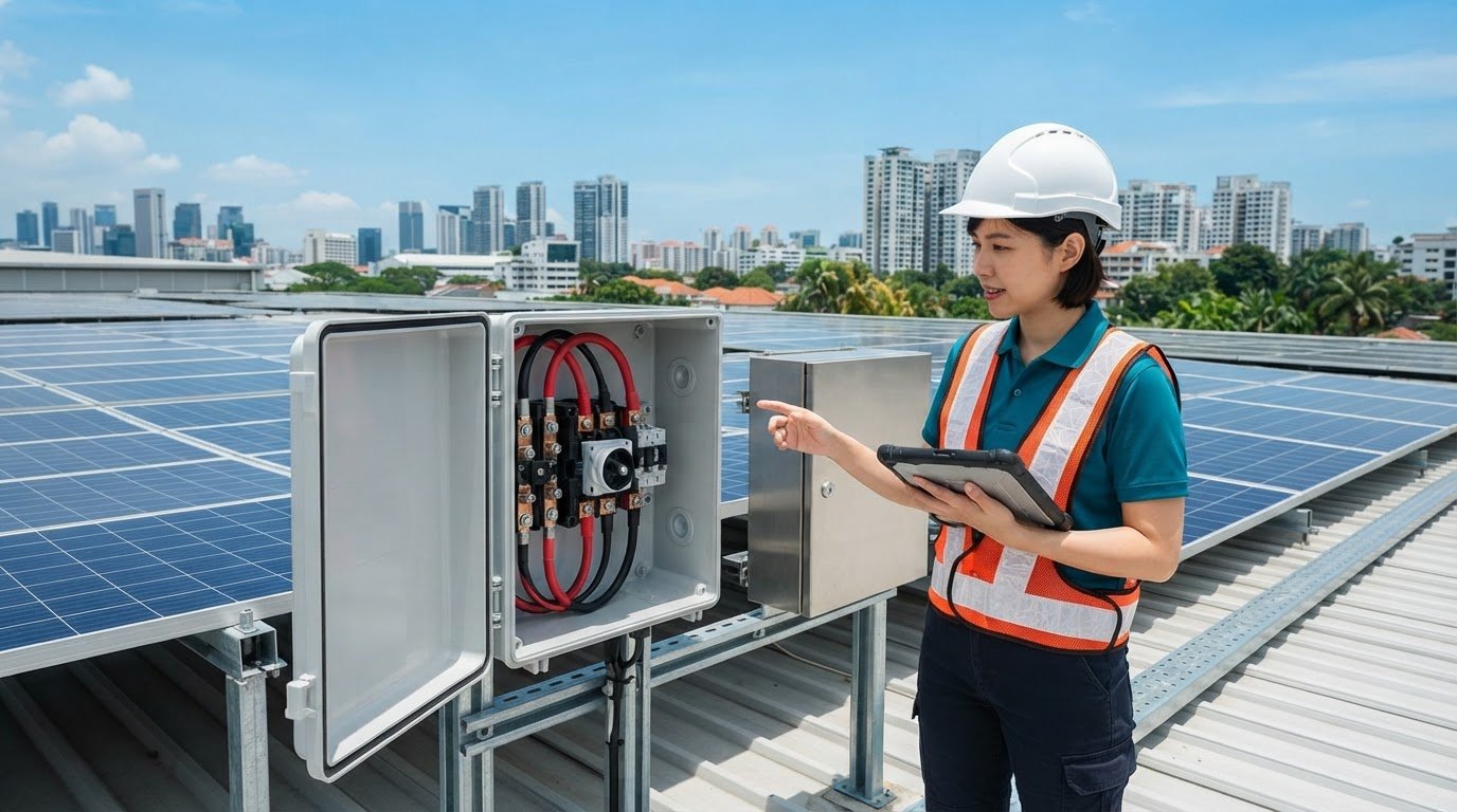
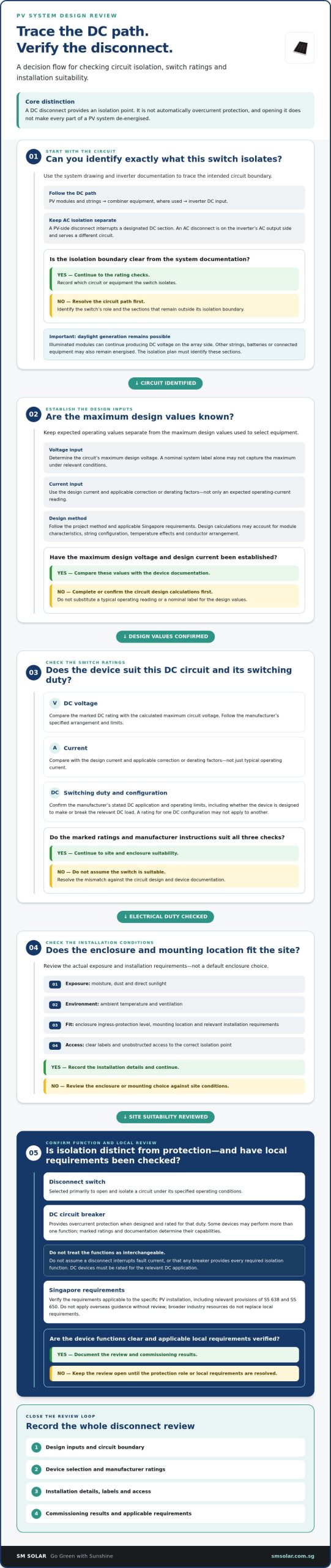
    A DC disconnect switch opens a selected direct-current circuit to provide an isolation point from downstream equipment. In a photovoltaic system, that point can support maintenance or fault response. Opening the switch doesn’t automatically de-energise every component: illuminated modules can continue producing DC voltage on the array side. Safe work depends on the system’s isolation plan and on identifying equipment that remains energised.

    For DC disconnect switches solar systems use, the function is isolation, not a general guarantee that a circuit is safe to touch. The role of a disconnector in electrical systems is described in What is a Disconnector? In a PV design, consider the switch alongside the circuit configuration, protection devices, inverter instructions and access for the people who may need to operate it.

    Where the DC disconnect fits in a solar array

    A typical DC path starts at PV modules, which may be wired into string circuits. Depending on the design, strings may connect through combiner equipment before reaching the inverter, where DC power is converted to AC. A PV-side disconnect interrupts a designated part of the DC path. An AC disconnect sits on the inverter’s AC output side and serves a different circuit.

    There isn’t one universal arrangement. A system may have isolation points at different equipment or circuit boundaries, depending on its configuration and applicable requirements. Use the system drawing and inverter documentation to identify what each switch isolates. Clear labels and unobstructed access help maintenance personnel find the correct point, while the isolation procedure should identify any sections that remain energised.

    • Modules and strings: DC generation begins here, and conductors may remain energised in daylight.
    • Combiner equipment: Where used, it brings multiple strings together and may include circuit protection.
    • Inverter: Receives DC input and supplies converted AC power to the downstream system.

    Review placement as part of the complete circuit path, not from a generic diagram alone. A switch on the PV side doesn’t replace the AC isolation point. Operating one switch also doesn’t necessarily isolate other strings, batteries or equipment connected elsewhere in the system.

    Disconnect switch versus DC circuit breaker

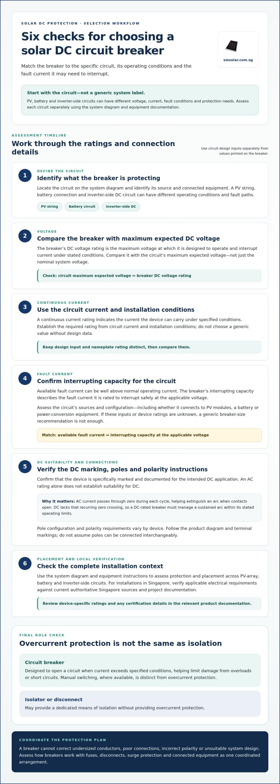
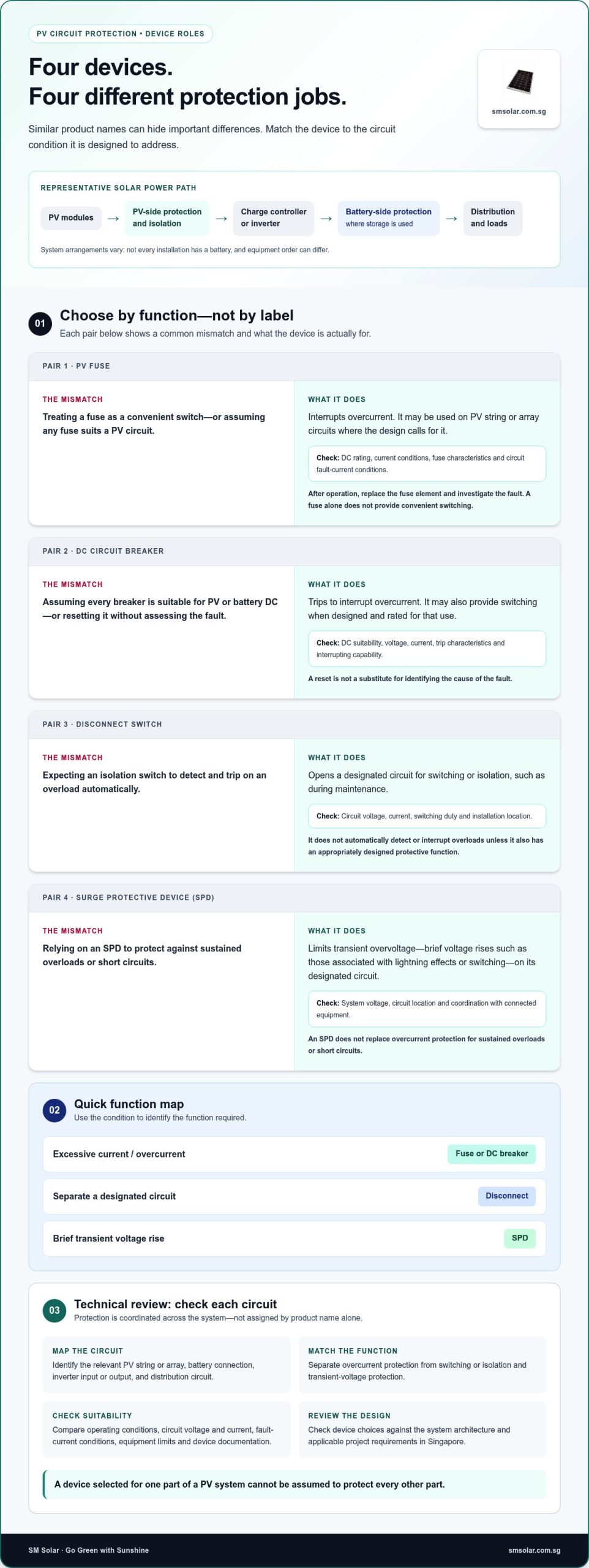
    A disconnect switch is selected primarily to open and isolate a circuit under its specified operating conditions. A DC circuit breaker provides overcurrent protection when designed and rated for that duty. Some devices may perform more than one function, but their marked ratings and documentation determine their capabilities. Don’t assume a disconnect will interrupt fault current or that any breaker provides every required isolation function.

    Selection must account for the DC circuit, not just a familiar AC component or handle style. DC arcs behave differently from AC arcs, so the device must be rated for the relevant DC application. Keep isolation and overcurrent protection separate in the design review. For breaker-specific selection considerations, see the DC circuit breaker selection and safety guide.

    Which DC Disconnect Ratings Must Match the Solar Circuit?

    A switch’s headline voltage and current values are only a starting point. Selection depends on the circuit it will isolate, conditions at the installation location and the device’s specified DC switching duty. Record the design inputs first, then compare them with the manufacturer’s datasheet and installation instructions.

    Keep normal operating values separate from maximum design values. Array operating voltage and current describe expected conditions, but they may not represent the worst case used for equipment selection. Design calculations may account for module characteristics, string configuration, temperature effects and conductor arrangement. Follow the method required by the project design and current Singapore requirements, rather than applying a sizing rule from another jurisdiction. SEIA’s Solar Industry Codes and Standards resource offers broader industry context, but it doesn’t replace local requirements.

    Voltage, current, and switching capacity

    Check that the disconnect’s rated DC voltage is suitable for the circuit’s maximum design voltage. A nominal system label alone may not capture the maximum voltage under relevant conditions. Compare the documented design value with the device rating, following the manufacturer’s specified arrangement and limits.

    Review current in the same way. Don’t match a switch to a typical operating-current reading without checking the circuit design and applicable derating factors. Confirm the rating for the intended switching duty, including whether the device is designed to make or break the relevant DC load. A rating for one DC configuration may not apply to another.

    • Voltage: Compare the marked DC rating with the calculated maximum circuit voltage.
    • Current: Use the design current and applicable correction or derating factors, not just expected operating current.
    • Switching duty: Verify the manufacturer’s stated DC application and operating limits.

    Enclosure and installation conditions

    Electrical ratings aren’t the only consideration. Assess whether the enclosure and mounting location suit the actual exposure, including moisture, dust, direct sunlight, ambient temperature and ventilation. Match the ingress-protection level to site conditions and relevant installation requirements instead of choosing one by habit.

    Check the physical connections too. Confirm compatibility with conductor material and size, terminal capacity, tightening instructions, cable entry and required clearances. Review polarity markings and the wiring diagram, especially if the device uses multiple poles or a specific pole arrangement. The number of poles must suit the circuit configuration and intended isolation. Incorrect connections can undermine an otherwise suitable rating.

    Keep a record of the design voltage, design current, circuit configuration, conductor details, environmental conditions, device ratings and manufacturer instructions. Resolve mismatches before procurement or installation. For current Singapore projects, verify applicable local requirements and their editions through the project documentation and qualified design process. Overseas guidance does not automatically transfer. Coordinating solar circuit-protection hardware with the wider PV specification helps align component selection with the system design.

    How Does a DC Disconnect Compare With Other Solar Protection Devices?

    PV systems use devices that may look similar on a single-line diagram but serve different functions. A disconnect provides a means of isolation; a circuit breaker may interrupt overcurrent; an AC disconnect isolates an AC circuit; and a combiner box brings PV strings together. The equipment and coordination depend on the system design, equipment documentation and applicable requirements in Singapore.

    Component Typical circuit location Primary function Protection role
    DC disconnect PV DC circuit, at a designed isolation point Open and isolate a DC circuit for service or other specified operation Isolation; don’t assume it provides overcurrent protection
    DC circuit breaker DC circuit, as specified in the system design Interrupt current under defined operating conditions Provides overcurrent protection when designed and rated for that function
    AC disconnect Inverter AC output or another designated AC circuit Isolate the AC side of equipment Isolation on an AC circuit; not a substitute for a DC-rated device
    Combiner box Where multiple PV strings are brought together Combine string circuits into an output circuit May contain protective or isolation devices, depending on its design

    DC disconnects and overcurrent protection

    Separate the isolation task from the overcurrent task during design review. A switch handle that opens a circuit doesn’t show, by itself, that the device will respond to overload or fault current. Likewise, a breaker’s protective function doesn’t establish that it meets every required isolation arrangement. Check the device markings, ratings and manufacturer documentation, then confirm each function against the circuit design. Don’t treat components as interchangeable without design evidence.

    For a broader view of how protective devices fit together, consult this solar circuit protection devices guide. The DOE Solar Codes and Standards resource provides general context on codes and standards for solar systems. It doesn’t replace checking current Singapore requirements for a local project.

    Disconnects and solar combiner boxes

    A combiner box is an assembly point, not another name for a disconnect. It collects multiple PV string circuits where the system configuration calls for it. The enclosure may include string-level protective devices, an isolation device or other components, depending on the assembly and design. Identify the actual components and the conductors each one affects.

    For example, a disconnect associated with a combiner assembly may isolate a defined output, while string protective devices serve different circuit functions. Don’t assume that opening one component isolates every string or every connected energy source. Review the single-line diagram and equipment documentation together. This solar combiner box components guide covers assembly roles in more detail.

    Assess DC disconnect switches solar systems require as part of coordinated hardware selection, not as standalone components. Match each device to its circuit, function and rating, then confirm the arrangement against the project design and current applicable requirements.

    Solar DC Disconnect Switches: A Practical Selection Checklist

    Solar DC Disconnect Switch Checklist: From Design Review to Commissioning

    Review the disconnect across four stages: design inputs, device specification, installation and verification. This keeps selection tied to the PV circuit and its documentation rather than relying on a headline rating alone. For DC disconnect switches solar projects use, record the basis for each decision so it can be traced through procurement, installation and handover.

    Before specifying or purchasing the switch

    Start with the approved PV array and inverter documentation. Use the single-line diagram and equipment instructions to identify the circuit the switch must isolate, its location in the DC path and any connected sources relevant to isolation. Record the design values and configuration before comparing devices.

    • Design inputs: Capture maximum design voltage, operating current, string or array configuration, and the applicable calculation assumptions.
    • Circuit details: Note conductor material and size, polarity, number of poles, terminal requirements, and protective devices that must coordinate with the switch.
    • Device specification: Compare DC voltage and current ratings with the design values. Confirm the manufacturer’s stated switching duty and operating limits for the intended circuit.
    • Installation environment: Document the mounting location, exposure to moisture, dust and temperature, enclosure needs, cable entry and required clearances.

    Separate normal operating readings from maximum design values. Use the project’s applicable calculations and correction factors. Don’t select a switch based solely on a typical production reading. Keep the datasheet, wiring diagram and inverter instructions with the selection record. Resolve any unclear rating, terminal detail or intended switching function through the project’s technical review before procurement.

    Installation and handover checks

    At installation, compare the actual device and wiring with the approved design and manufacturer instructions, and record any approved change. Check that the switch is positioned for its intended isolation function and can be reached without moving equipment or encountering avoidable obstructions.

    • Verify device identification, polarity markings, labels and circuit references against the drawings.
    • Confirm conductor and terminal compatibility, follow the specified termination method, and maintain required clearances.
    • Inspect the enclosure, cable entries and mounting for suitability at the installed location.
    • Document the isolation procedure, including which PV sections or other sources may remain energised.
    • Record applicable commissioning checks, results, drawing updates and the responsible qualified personnel.

    Commissioning scope and acceptance criteria must follow the project design, equipment documentation and current Singapore requirements. Verify the applicable code provisions and standard editions for the installation. Don’t transfer foreign code guidance without checking its local relevance. A complete handover record should help future maintenance personnel identify the correct isolation point and understand its limits.

    For coordinated solar hardware and circuit-protection requirements, review SM Solar’s solar products alongside the PV system specification.

    How SM Solar Supports Solar DC Protection Hardware Requirements

    Disconnect selection is one part of a wider PV hardware specification. The switch must correspond to the circuit it isolates and coordinate with the system’s other DC equipment. Review the complete design rather than treating one component’s rating as a substitute for the array, storage or inverter documentation.

    Specify disconnect hardware as part of a complete PV design

    In a PV system, modules, charge controllers, batteries and inverter architecture shape the DC circuits and their isolation needs. A system with storage, for example, has different equipment paths to account for than a grid-connected array without a battery. Map those paths using the project’s diagrams and equipment documents before specifying protection hardware.

    SM Solar is a wholesale distributor of solar products, including circuit protection devices and other DC-related products. Its product range supports solar hardware projects where components need to be considered as part of a coordinated specification. The right switch and protection arrangement depend on the documented project requirements, manufacturer information and current Singapore requirements.

    For DC disconnect switches solar projects require, keep the switch’s isolation role distinct from the functions of breakers and other protective devices. A coordinated review considers the relevant circuit boundaries, system configuration and equipment interfaces together. SM Solar also provides system integration, connecting component requirements to the broader system design.

    Move from technical checklist to project requirements

    Before beginning a hardware specification, assemble the key project inputs in one place. This makes technical review more traceable and helps align product selection with the PV design.

    • System configuration: Record module strings, combiner arrangements, charge controllers, battery connections and inverter architecture.
    • Electrical design: Document maximum circuit voltage, operating current, applicable design calculations and protection coordination.
    • Installation details: Identify conductor and terminal requirements, mounting location, enclosure conditions, labels and access needs.
    • Reference documents: Keep current drawings, equipment datasheets, inverter instructions and the project’s applicable Singapore compliance requirements together.

    SM Solar distributes solar hardware and provides installation and after-sales maintenance for end users. These capabilities complement its wholesale supply role. Project-specific design checks and verification of current local requirements remain part of the system design process. Clear circuit and equipment details provide a useful basis for coordinating solar circuit protection with the rest of the system.

    For solar hardware aligned with your project requirements, explore SM Solar’s solar hardware range.

    Carry the Specification Into Your Next PV Project

    Make the disconnect decision part of the project’s documented design handoff. Keep the selected device, circuit references and isolation procedure aligned as drawings or equipment configurations change. This gives procurement, installation and future maintenance teams a consistent basis for reviewing the system.

    For projects in Singapore, include standards and code checks in that handoff. Verify the requirements and editions applicable to the installation rather than relying on assumptions from another market. A clear technical record helps keep DC disconnect switches solar systems use matched to their intended circuit and role.

    Established in 2008, SM Solar supports solar hardware projects through wholesale distribution of circuit protection and other DC-related products. The company also provides system integration, installation and after-sales maintenance for end users. To align component requirements with your project documentation, review SM Solar’s solar hardware range.

    A well-documented specification gives your PV project a consistent basis for coordinated hardware decisions.

    Frequently Asked Questions

    What does a DC disconnect switch do in a solar PV system?

    It opens a designated DC circuit to create an isolation point, such as between PV equipment and an inverter. This can support inspection, maintenance or fault response, but it doesn’t mean every part of the array is de-energised. Modules exposed to light may still produce voltage upstream of the open switch. Follow the system’s isolation procedure and identify connected sources before work begins.

    Is a DC disconnect switch the same as a DC circuit breaker?

    No. A disconnect switch provides circuit isolation, while a DC circuit breaker provides overcurrent protection when designed and rated for that purpose. A breaker’s open position alone doesn’t establish that it performs every required isolation function. Check the device’s markings and technical documentation for its intended role. In a design review, identify each function separately and confirm that the specified equipment covers the circuit’s protection and isolation needs.

    Where should a solar DC disconnect switch be installed?

    Its position depends on the PV circuit, equipment layout and applicable project requirements. Use the single-line diagram to identify the intended isolation boundary, then compare that point with the inverter and other equipment instructions. The switch should be identifiable and accessible for its intended operation. Don’t assume that opening a PV-side switch also isolates the inverter’s AC circuit, battery connections or other DC sections.

    How do you size a DC disconnect switch for solar panels?

    Compare its DC voltage and current ratings with the circuit’s maximum design values, using the project’s calculations rather than typical operating readings alone. Account for the array configuration, relevant temperature effects and applicable derating factors. Also check the pole arrangement and switching duty against the manufacturer’s documentation. For DC disconnect switches solar projects require, check the final selection against current Singapore requirements and the approved system design.

    Can a solar DC disconnect switch interrupt current under load?

    Only if its documentation specifies switching capability for the relevant DC load and operating conditions. A device intended only for isolation under particular conditions may not be suitable for routine load switching. Check the manufacturer’s stated making and breaking duties, ratings and operating instructions. If the system procedure requires opening the switch while current is flowing, verify that this operation is within the device’s specified use.

    Does every solar PV system need a separate DC disconnect?

    Not necessarily as a separate standalone enclosure or component. The required isolation arrangement depends on the system architecture, equipment design and current requirements applicable to the installation. Some equipment may include an isolation function, but its presence doesn’t automatically establish that the overall system meets its requirements. Review the inverter documentation, circuit diagrams and project compliance basis to determine which isolation points are required and what each one disconnects.

    What should be checked before commissioning a solar DC disconnect?

    Confirm the installed device matches the approved design and manufacturer instructions. Check circuit identification, labels, polarity, conductor and terminal compatibility, enclosure condition, mounting and access. Ensure the documented isolation procedure identifies what remains energised when the switch is open. Record the commissioning checks and results with any drawing updates. The responsible qualified personnel should verify the checks and compliance basis against current Singapore requirements for the specific project.

  • Solar Combiner Box Components: Functions, Selection and System Integration

    Solar Combiner Box Components: Functions, Selection and System Integration

    A solar combiner box is defined not just by its parts list, but by how its components work together. Solar combiner box components can include string fuses, busbars, a DC disconnect, surge protection, terminals and monitoring devices. The right arrangement depends on the PV system design. Selecting components individually without checking their ratings and interfaces can create compatibility gaps between the array, combiner box, inverter and system wiring.

    To specify a box effectively, first identify which circuits it needs to combine and where its output will go. Then check which connection, protection and isolation functions belong in the assembly. This guide explains the role of common components, how array configuration influences selection, and what to review when specifying equipment for a project in Singapore.

    Use the practical checks below to coordinate component ratings and connections with string count, system voltage, inverter inputs and wiring. For projects that need coordinated DC hardware, SM Solar supplies solar components and provides system integration and installation for end users.

    Key Takeaways

    • Identify the main solar combiner box components and distinguish connection parts from protection and isolation devices.
    • Use string count and array layout to define the box configuration, then assess device ratings against the system design.
    • Review system documentation, component compatibility, enclosure, terminals and supporting documents before procurement.
    • Coordinate the combiner box with inverter inputs and PV wiring to reduce mismatches across the DC system.
    • SM Solar’s wholesale supply and system integration capabilities support coordinated sourcing for on-grid and off-grid projects.

    What Is a Solar Combiner Box, and Where Does It Fit in a PV System?

    A solar combiner box is a DC assembly that brings selected photovoltaic (PV) string circuits together at a common output. It sits between the PV array and downstream equipment, such as an inverter or a DC distribution point. Consolidating string outputs can reduce the number of separate circuit runs continuing from the array. The box also provides a defined location for connections and, where the design requires them, protective or isolation devices.

    A combiner box does not convert the array’s DC electricity into AC. That is the inverter’s role. Nor is it an AC distribution board, which distributes power on the AC side of a system. A fuse, disconnect or surge protective device has a specific circuit function; a combiner box is an assembly that may house selected devices alongside the connections. Its contents depend on the system architecture, circuit layout and design requirements.

    How does a combiner box connect PV strings?

    PV modules connected in series form a string, which creates an individual DC circuit from the array. The string conductors are routed to the combiner box and connected at designated points. The box brings selected circuits to a common output that continues toward downstream equipment. It consolidates the circuits but does not change the modules’ series arrangement within each string.

    Array topology determines whether a system uses one box, multiple boxes or another routing arrangement. For example, strings in separate array sections may go to different boxes before their outputs connect farther downstream. The design should show which strings terminate at each box and where each output goes. This circuit-level view helps distinguish the number of array strings from the number of combiner boxes required.

    Which systems use a solar combiner box?

    A combiner box is commonly used when a PV design has multiple string circuits to consolidate before they connect to downstream equipment. It can organise array wiring and provide a location for protection and isolation devices specified by the design. A system with fewer strings, or with an inverter and wiring arrangement designed to accept separate string inputs, may use a different layout. The equipment interfaces and project documents determine the suitable arrangement.

    Assess the box as part of the full DC circuit, not as a standalone enclosure. Review the array layout, inverter input arrangement, cable routing and protection strategy together. The solar circuit protection devices guide provides further context on protective devices in PV systems. Combining circuits may simplify connections, but it does not replace the need to select and coordinate suitable protection across the system.

    Before specifying the assembly, use the system diagram to identify which strings enter each box and where each combined output goes. Then determine which connection, protection and isolation functions the architecture requires. This establishes the box’s role in the PV system and provides a basis for reviewing its components.

    Solar Combiner Box Components and the Function of Each Part

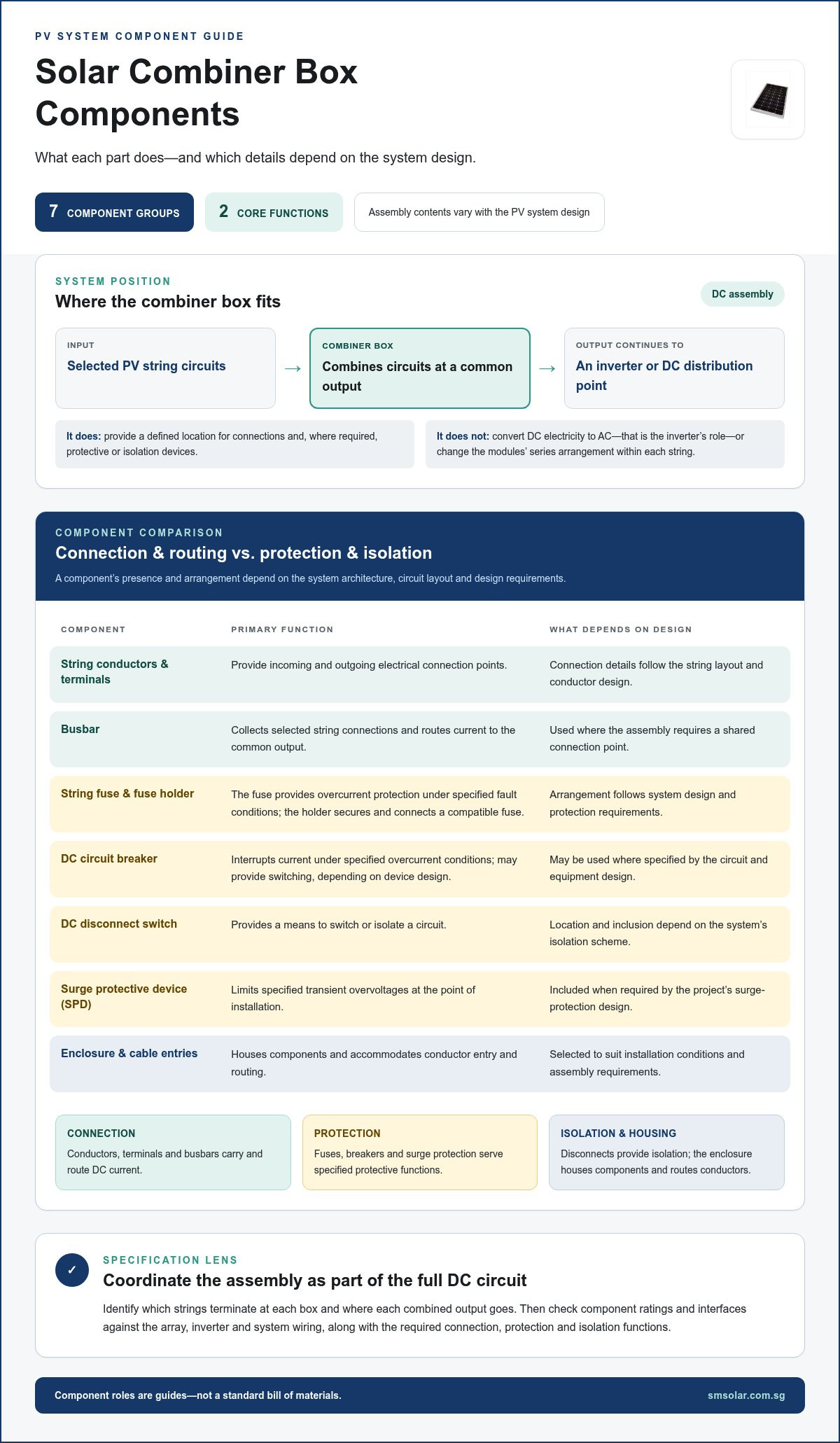
    Solar combiner box components serve two broad purposes: carrying and routing DC current, or providing protection and isolation. The assembly varies with the system. One design may use string fuses, a disconnect and surge protection, while another may place some of those functions elsewhere. Treat the list below as a guide to component roles, not a standard bill of materials.

    Component Primary function Configuration-dependent status
    String conductors and terminals Provide the incoming and outgoing electrical connection points. Required connection details depend on string layout and conductor design.
    Busbar Collects selected string connections and routes current to the common output. Used where the assembly design requires a shared connection point.
    String fuse and fuse holder Fuse provides overcurrent protection under specified fault conditions; holder secures and connects the compatible fuse. Required arrangement depends on system design and protection requirements.
    DC circuit breaker Interrupts current under specified overcurrent conditions and may provide switching, depending on device design. May be used where specified by the circuit and equipment design.
    DC disconnect switch Provides a means to switch or isolate a circuit. Location and inclusion depend on the system’s isolation scheme.
    Surge protective device (SPD) Limits specified transient overvoltages at the point of installation. Included when required by the project’s surge-protection design.
    Enclosure and cable entries Houses components and accommodates conductor entry and routing. Selected to suit installation conditions and assembly requirements.

    String fuses, fuse holders and busbars

    A string fuse is designed to protect its circuit against specified overcurrent conditions. Select it based on the PV circuit and equipment design, and confirm that it is compatible with its holder and suitable for the DC application. The holder provides the mechanical mounting and electrical interface. A busbar brings selected circuits together and carries the combined connection toward the box output. Check that the terminal arrangement and conductor capacity match the design documents.

    String protection limits fault current in a circuit. Circuit isolation provides a means to disconnect one part of the system from another. These functions are related but not interchangeable.

    DC circuit breakers, disconnects and surge protection

    A DC circuit breaker provides overcurrent protection, while a disconnect switch is intended to open or isolate a circuit. A breaker may also provide switching, but its protective function and rating must suit the application. Select devices using their documentation and the project design, not appearance alone. The DC circuit breakers for solar guide explains key selection considerations.

    An SPD addresses specified transient overvoltages; it does not replace overcurrent protection or circuit isolation. Its placement and coordination should follow the project design. For broader solar technology context, see the U.S. Department of Energy Solar Energy Technologies Office. For solar circuit protection and related DC hardware, explore SM Solar’s solar product range.

    How PV Design Changes Solar Combiner Box Component Selection

    Start combiner-box planning with the array and downstream equipment, not a standard parts list. String count and physical layout help determine how circuits are grouped and routed. They do not, on their own, set fuse, disconnect, conductor or busbar ratings. Those decisions require system design data, including circuit voltage, operating and fault current, and the inverter’s input limits.

    Design factor Effect on connection planning Effect on component selection
    String count Determines the incoming circuit connections and how they may be grouped. Informs the required number of connection points; it does not alone determine device ratings.
    Array topology and location Influences where circuits can be consolidated and how output cables route toward downstream equipment. Affects enclosure arrangement, terminal layout and cable-entry planning.
    System voltage Defines the electrical conditions across connected DC circuits. All relevant devices and insulation arrangements must suit the designed voltage.
    Operating and fault current Informs the expected current in each circuit and the combined output. Guides selection and coordination of conductors, busbars and protection devices.
    Inverter or controller interface Sets the destination and input arrangement for the combined circuits. Requires checking the equipment’s documented limits and connection requirements.

    String count, array topology and combining points

    Before choosing where circuits should combine, map each string to its array section, planned cable route and destination. If strings are spread across separate roof areas, for example, the design may route them to different combining points to suit cable paths or equipment interfaces. That does not prescribe a fixed number of boxes. Use the single-line diagram and site layout to establish the arrangement.

    Keep connection planning separate from rating decisions. A layout drawing can show how many circuits reach a box and where its output goes. Electrical calculations and equipment documentation establish the conditions each component must handle. Component ratings must match the designed circuit.

    Protection requirements and inverter interfaces

    Compare the inverter’s documented DC input voltage range, allowable current and input configuration with the array and proposed combiner output. Circuits can fit the terminals and still be incompatible with the inverter. For a system using a charge controller, review its PV input requirements against the array and downstream battery architecture. Include relevant fault conditions when assessing protective devices and conductor coordination.

    Protection coordination depends on the complete circuit design, including the PV source, conductors, protective devices and receiving equipment. Do not select a fuse or breaker based on string count alone. Check device ratings and coordination against project documents and the electrical requirements applicable to the installation in Singapore. The National Electrical Code (NFPA 70) is a U.S. code reference, not a substitute for confirming requirements that apply to a Singapore project.

    Solar Combiner Box Components: Functions, Selection and System Integration

    How to Specify and Review a Solar Combiner Box

    Use a traceable review process: start with approved system documents, turn their requirements into a component specification, then compare the supplied assembly with the approved design before installation and commissioning. Keep design verification separate from physical inspection. A box can look complete while containing a device or connection arrangement that does not match the project.

    What information belongs in the specification?

    Build the specification from the array schedule, single-line diagram, circuit calculations and inverter documentation. Record the string arrangement, circuit voltage and current data, expected fault conditions, output destination, cable routes and installation environment. These details provide the basis for selecting solar combiner box components without assuming a standard configuration.

    Use approved design documents to identify protective-device characteristics, isolation requirements and coordination. Specify enclosure conditions, cable-entry positions, terminal types, conductor ranges and labelling needs as required for the project. Check the codes and standards that apply to the Singapore project rather than importing requirements from another market.

    Use this review sequence:

    1. Establish the design basis. Confirm the current approved drawings, array schedule, circuit data and equipment documentation.
    2. Translate requirements. Record the required string connections, output arrangement, protection and isolation functions, environmental conditions and interface limits.
    3. Compare selections. Match proposed device ratings and connection details to the design calculations and receiving equipment requirements.
    4. Review the assembly. Check the enclosure, terminals, entries, labels and component identification against the specification.
    5. Record discrepancies. Resolve differences through the project’s document-control and approval process before installation proceeds.

    What should be checked before commissioning?

    Physical inspection verifies the delivered and installed assembly, but does not replace design approval. Compare the component schedule and approved drawings with the actual devices. Check for visible damage, correct wiring identification, secure and correctly located conductors, clear labels, suitable cable entries and proper enclosure closure. Confirm that the assembly’s location and connections align with the project drawings.

    Follow the applicable project procedures and equipment documentation for commissioning tests, methods and acceptance criteria. Record inspection findings and approved changes so the final installation remains traceable to its design. A visual check alone does not verify electrical performance or protection coordination.

    Specification checklist

    • System voltage, circuit current and fault-condition data correspond to approved design documents.
    • Protective and isolation devices suit their assigned circuits and the inverter or controller interface.
    • Enclosure, cable entries, terminals, conductor ranges and labelling meet project requirements.
    • Device markings, drawings and technical documents match the supplied assembly.
    • Applicable jurisdictional requirements and project acceptance procedures are identified.

    For coordinated sourcing of solar circuit protection and related DC hardware, explore SM Solar’s solar products.

    Sourcing and Integrating Combiner Box Components with SM Solar

    Combiner-box selection connects several parts of a PV system. Fuses, disconnects, surge protection, conductors and terminals must suit the circuit design and work with downstream equipment. Coordinated sourcing lets project teams review these relationships together instead of treating each DC component as a separate purchase. Use the specification as the basis for selection, and compare component ratings, interfaces and documentation with the approved design before procurement and installation.

    This coordination applies to both on-grid and off-grid systems. A combiner-box output may connect to an inverter or, in a system that uses one, a solar charge controller. The interface affects the protection and connection arrangements required across the wider DC system. Reviewing related equipment documentation together can help identify mismatches in ratings, connection points or intended functions before assembly.

    Coordinate protection hardware with the wider DC system

    Review the protection strategy across the full DC path, from array circuits through the combiner assembly to the receiving equipment. Each protective device must suit its circuit and function, and the inverter or controller interface shapes the connection plan. For an overview of how protective devices fit into PV design, consult the solar circuit protection devices guide.

    If the system uses a solar charge controller, compare its input requirements with the array design and related DC equipment. The MPPT solar charge controller specifications guide can support that review. Keep device ratings, protection coordination and connection details tied to project documents. A general product category alone does not establish compatibility.

    SM Solar’s supply and project support

    SM Solar is a wholesale distributor of solar products, including solar circuit protection and other DC-related hardware. Its product range also includes solar panels, charge controllers and hybrid inverters. SM Solar provides system integration, installation and after-sales maintenance for end users, supporting projects that need product supply alongside these capabilities.

    Before comparing components, document the array configuration, circuit data, receiving equipment, environmental conditions and required protection functions. Then assess products against the approved specification and record any design differences for review. This gives the project team a clear basis for sourcing without assuming every system needs the same combiner-box arrangement or component set.

    Explore SM Solar’s solar products to review equipment for your PV system requirements.

    Move from Specification to a Coordinated PV Design

    Use approved system documents to connect design decisions with procurement. Before placing orders, turn the combiner-box schedule into a clear component and connection record, then align it with the array layout, downstream equipment interfaces and installation drawings. This gives the project team a shared reference for managing design changes and maintaining traceability through assembly and commissioning.

    Apply the same approach when reviewing solar combiner box components alongside other DC hardware. Record approved substitutions or revisions, and ensure updated documents reach the people responsible for procurement, integration and installation. For engineering teams managing broader bills of materials or sourcing discrete electronic parts for power systems, Adage Components provides dedicated component distribution and BOM support. A consistent record keeps decisions visible as the project moves from specification to site work.

    For your next PV project, let the system design guide sourcing and coordination. Explore SM Solar’s solar products to plan the equipment required for your application.

    Frequently Asked Questions

    What components are commonly found in a solar combiner box?

    Common solar combiner box components include string terminals, busbars and an enclosure. Fuses and other protective devices are included when the design calls for them. Some assemblies also include a disconnect, surge protection or monitoring. For example, a project may specify current monitoring to compare string performance. The equipment schedule and circuit diagram show which functions belong in the box and which are provided elsewhere in the PV system.

    Are string fuses required in every solar combiner box?

    No. String fuses are not automatically required in every box. Their use depends on the array configuration, possible fault-current paths and the system’s documented protection strategy. A designer may assess whether parallel-connected strings could expose a circuit to current from other strings during a fault. Use the approved electrical design and equipment instructions to determine whether fuses are needed and which characteristics suit the application.

    What is the difference between a combiner box and a DC disconnect?

    A combiner box is an assembly that may bring several PV circuits together and house selected devices. A DC disconnect is a switching device intended to open or isolate a DC circuit. Depending on the design, a disconnect may be installed inside a combiner enclosure or elsewhere in the system. Do not assume that a combiner box provides isolation unless the specified assembly includes a suitable disconnect function.

    Does every solar system need a combiner box?

    No. A combiner box is useful when the design calls for multiple PV string circuits to be consolidated, but another arrangement may suit systems with fewer strings or equipment that accepts separate string inputs. For example, an inverter with suitable independent inputs may receive array circuits without a separate combining enclosure. The single-line diagram and equipment connection requirements determine whether a box is needed.

    Where is a solar combiner box installed?

    A combiner box is installed on the DC side of the system, where it suits the array wiring and route to the receiving equipment. Its location depends on cable routes, access for inspection and maintenance, mounting conditions and the approved layout. For outdoor installations, the design should account for exposure to rain, moisture, heat and other site conditions while maintaining safe access and suitable cable entry arrangements.

    Can a charge controller connect to a solar combiner box?

    Yes, if the system routes combined PV circuits to a charge controller and the controller’s PV input supports the resulting electrical conditions. Check its input limits, polarity, connection arrangement and required protective devices against the controller documentation and system design. A combiner box does not replace the controller or determine battery-side wiring. Keep the PV input path distinct from the controller’s battery connections.

    What enclosure rating should a solar combiner box have?

    No single enclosure rating suits every installation. Select an enclosure based on exposure, mounting position, moisture and dust risks, temperature conditions and any corrosive agents at the site. For outdoor projects in Singapore, account for weather exposure in the design. Compare the enclosure’s documented protection rating with project requirements, installation conditions and applicable local requirements rather than choosing by appearance alone.

  • MPPT Solar Charge Controllers: How to Compare and Specify the Right Unit

    MPPT Solar Charge Controllers: How to Compare and Specify the Right Unit

    A controller’s amp rating may look suitable, but its PV input limit or battery compatibility could rule it out. Selecting MPPT solar charge controllers means checking how the array’s voltage and power, the battery bank’s nominal voltage, and the controller’s output capacity work together.

    It’s also useful to compare MPPT with PWM before specifying a system. MPPT controllers convert the array’s operating voltage to suit battery charging, within the unit’s stated limits. That flexibility can support array and battery configurations that a PWM controller may not suit, but it doesn’t remove the need to check maximum PV open-circuit voltage, charge settings, and output current.

    This article explains how MPPT tracking and conversion work, where their limits apply, and how to compare MPPT and PWM for a specific design. It then outlines what to gather before procurement, including panel configuration, battery chemistry and voltage, array power, and operating requirements. Use this sequence to identify a controller that fits the complete PV and battery system.

    Key Takeaways

    • MPPT solar charge controllers adjust the PV array’s operating point. Assess battery charging regulation and protection as separate functions.
    • Compare MPPT and PWM against the array and battery configuration rather than treating either technology as the universal choice.
    • Before reviewing controller models, record panel electrical data, array configuration, battery chemistry and voltage, and project operating requirements.
    • Check each candidate’s PV input limits, charging compatibility, and output ratings against the complete system design.
    • A finalized specification supports accurate sourcing of the controller alongside related PV, battery, and DC components.

    What MPPT Solar Charge Controllers Do in a PV System

    Maximum power point tracking (MPPT) is a control method that adjusts a solar array’s operating voltage and current to access the greatest power available under current conditions. In a PV system, an MPPT charge controller manages the electrical transfer from the modules to a battery bank, within the controller’s operating limits and the battery’s charging requirements.

    Where the MPPT controller sits in the system

    In a DC-coupled battery system, energy typically flows from the PV modules to the charge controller and then to the battery. The controller is distinct from both: modules generate DC electricity, while the battery stores it. An inverter converts DC power to AC for compatible loads. Depending on the system topology, the inverter may connect to the battery or include its own PV charging function, so the equipment connection diagram matters.

    The controller regulates the PV-side input and the charging output to the battery. It isn’t the PV array, an energy-storage device, or an inverter. MPPT solar charge controllers must suit the equipment they connect to, including the array configuration and battery requirements. The Maximum Power Point Tracking (MPPT) overview provides further background on the method and its use in PV systems.

    What maximum power point tracking means

    A panel’s electrical output depends on its operating voltage and current. Multiplying them gives power. The maximum power point is the voltage-current operating point at which the panel or array can deliver the most available power under a particular set of conditions. The controller adjusts the PV operating point as conditions change, while converting the input to a form suitable for battery charging.

    Available output varies with factors such as sunlight, module temperature, and shading. Tracking responds to changes in the array’s output, but it doesn’t remove their effects. Partial shading can still reduce generation, and an unsuitable array layout can still create electrical or compatibility issues.

    For specification, keep the system boundaries clear. PV voltage and current describe the controller’s input conditions. Battery chemistry, nominal voltage, and charging requirements shape the output side. The controller must suit both, with its limits aligned to the connected equipment. These relationships provide a starting point for comparing controller types and reviewing candidate specifications.

    How MPPT Tracking Works, and What It Cannot Solve

    An MPPT controller measures the PV array’s electrical behaviour and adjusts its operating point to track where voltage and current produce the greatest available power. As irradiance or module temperature changes, the relationship between voltage and current changes too. Tracking responds to those shifts within the controller’s operating range; it doesn’t increase the energy the modules can generate beyond what conditions allow.

    MPPT benefits depend on system configuration and operating conditions, not on the controller alone. This distinction matters when estimating system output or comparing models. Tracking is only one part of the controller’s role in a PV-to-battery system.

    PV input and battery-side output

    Evaluate the controller’s PV input and battery output as separate specification groups. The PV side has limits for values such as input voltage and current, which must suit the array and its configuration. On the battery side, output current, nominal voltage, and supported charging settings must align with the battery requirements.

    The controller uses power electronics to convert PV input into a suitable battery-charging output. Input voltage and output voltage therefore aren’t interchangeable ratings. The controller also regulates charging, while protection functions vary by model. Review the current product documentation for each candidate’s exact limits, charging behaviour, and protection features.

    Operating conditions and practical limits

    Available PV power changes with irradiance, module temperature, and the electrical arrangement of the array. The controller tracks the array’s operating point as input conditions shift, but shading can still reduce generation. Array layout and string configuration also affect the voltage and current reaching the controller.

    MPPT cannot correct mismatched equipment or poor system design. An array that exceeds the controller’s input limits remains unsuitable; tracking doesn’t make it compatible. Likewise, the controller doesn’t add battery storage capacity or perform the inverter’s task of converting DC electricity to AC. Each component has a separate function.

    When comparing MPPT solar charge controllers, distinguish tracking, charging regulation, and protection in the technical specifications. First confirm that the PV input limits suit the planned array, then assess battery-side settings and ratings against the selected battery. Don’t assume a feature or operating limit from a general category description; use the manufacturer’s documentation for the specific unit.

    Once the array and battery requirements are clear, compare compatible solar charge controllers as part of the wider system specification.

    MPPT vs PWM Solar Charge Controllers: Compare by System Requirements

    MPPT and PWM controllers both manage charging from a PV array to a battery, but they handle the relationship between PV input and battery charging differently. The useful comparison isn’t based on the technology label alone. Consider whether each controller’s operating approach and documented limits suit the array, battery, and expected operating conditions.

    Which technical differences matter during comparison?

    An MPPT controller adjusts the array’s operating point and converts the PV input to a battery-compatible output. A PWM controller regulates charging by controlling the connection between the array and battery. This difference affects how array voltage relates to battery charging voltage. Review the design and documentation for each candidate rather than assuming a controller category determines compatibility.

    Comparison point MPPT PWM
    Operating approach Tracks the PV operating point and converts input for battery charging. Controls the array-to-battery connection during charging; PV operating voltage is more closely tied to battery voltage.
    System compatibility Assess array voltage and current, battery voltage, and controller input and output limits. Assess array and battery voltage compatibility, along with the controller’s charging requirements and ratings.
    Selection considerations Review array configuration, battery charging settings, and documented operating limits. Review the same system requirements, with particular attention to how the array voltage suits the battery configuration.

    The table describes general operating approaches, not model specifications. Check maximum input voltage, current limits, and other model-specific values in current manufacturer documentation. A comparative performance claim is useful only when based on verified, comparable product data and relevant test conditions.

    How system context changes the decision

    Start with the system, not the controller label. Record the array’s configuration and electrical data, the battery’s chemistry and charging requirements, and the intended operating conditions. Then check whether each controller’s input and output ratings fit. For example, if an array is designed to operate at a voltage above the battery’s charging voltage, the controller’s conversion approach and input limits become important review points. Compatibility still depends on the specific unit.

    Module type is one part of the array specification. Monocrystalline solar panels still need to be assessed using their electrical ratings and planned series or parallel arrangement; the technology label alone doesn’t establish controller compatibility. MPPT solar charge controllers may suit some array and battery configurations better, while PWM may fit others. Select based on documented system fit, not a universal efficiency claim.

    MPPT Solar Charge Controllers: How to Compare and Specify the Right Unit

    How to Specify an MPPT Solar Charge Controller for a Project

    A reliable specification starts with the complete PV and battery design, not a controller’s headline rating. Use this workflow to gather the required information, screen candidate units, and identify system-interface issues before procurement.

    Collect the system data before procurement

    1. Document the PV array. Record the module model, electrical ratings, and planned series and parallel configuration using approved module documentation. Capture values such as open-circuit voltage, operating voltage, short-circuit current, and operating current. Include the temperature data needed to assess array voltage across expected conditions.
    2. Document the battery bank. Record battery chemistry, nominal voltage, configuration, and the manufacturer’s charging requirements, including permitted charge settings and current limits. The controller must support the battery’s charging profile.
    3. Map the system interfaces. Note how the controller connects with the inverter, battery, PV disconnects, and DC loads. Record relevant inverter or load requirements and clarify whether the system topology includes other charging sources.
    4. Record site and installation conditions. Include equipment location, expected temperature range, exposure to moisture or dust, cable routes, and approximate cable lengths. Use these details to assess environmental suitability and wiring design.

    Check compatibility, protection, and commissioning

    1. Screen candidate specifications. Compare the array’s documented voltage and current with the controller’s PV input limits. Then check its battery-voltage range, output-current rating, and supported charging settings against the battery documentation. Review all limits for the actual array configuration and operating conditions.
    2. Coordinate wiring and protection. Review conductor sizing, isolation, and overcurrent protection across the PV and battery circuits. Assess solar circuit protection devices, including DC circuit breakers for solar, as coordinated parts of the design. Determine ratings and placement using system documentation and applicable project requirements.
    3. Plan commissioning checks. Use the controller and component manuals to verify connections, polarity, configuration, and programmed battery settings. Record the final settings and confirm that the equipment operates as intended. Follow the manufacturers’ instructions and project requirements rather than applying assumed values.

    This process gives each candidate a clear pass-or-review basis and reduces the risk of comparing units against incomplete system data. For project-based sourcing, discuss your controller and system specification alongside the PV, battery, and DC components it must integrate with.

    Sourcing MPPT Solar Charge Controllers Through a Project-Based Supply Partner

    A finalized system specification gives controller sourcing a clear technical basis. It lets you assess the selected unit against the PV array, battery, protection devices, and system interfaces, rather than choosing by a headline rating alone. For MPPT solar charge controllers, this coordination keeps procurement focused on documented input and output requirements across the complete system.

    Coordinate the controller with the wider equipment set

    Controller requirements connect directly to the panel configuration and battery charging profile. Array voltage and current must fall within the controller’s documented PV input limits. Battery chemistry, nominal voltage, and manufacturer charging requirements must align with its output settings and ratings. For a project using a lithium LiFePO4 battery supplier, battery documentation is an essential input to that assessment.

    Protection devices, wiring, and system topology also form part of the equipment set. Review these alongside the controller, panels, batteries, and inverter, using the relevant product documentation to assess compatibility. SM Solar supplies solar charge controllers and related DC products, including panels, batteries, and solar circuit protection devices. The company also provides system integration, installation, and after-sales maintenance for end users.

    Prepare a clear procurement brief

    A useful procurement brief separates mandatory requirements from preferred features. Include:

    • PV module electrical ratings and array configuration
    • Battery chemistry, nominal voltage, and charging requirements
    • Controller input and output limits required by the design
    • Inverter, load, protection, and system-interface details
    • Installation location, environmental conditions, and wiring context
    • Preferred features that are not essential to system compatibility

    Use the brief to compare candidate specifications with the system documentation. Treat compatibility as a documented match, not an assumption based on product category. Keep optional preferences separate so they don’t displace essential requirements such as suitable input limits, battery settings, and interfaces. If datasheets and project documents differ, resolve the discrepancy before procurement.

    SM Solar’s wholesale supply and project capabilities connect controller sourcing with broader equipment selection and system integration. Review SM Solar’s solar charge controllers, related DC products, and project support against your finalized specification. This provides a practical starting point for aligning procurement with the PV and battery design.

    Specify the Controller Around the Complete System

    Choosing MPPT solar charge controllers starts with the relationship between the PV array, battery, and controller, not a standalone rating. Compare MPPT and PWM against the system’s actual configuration, then check candidate input and output limits against component documentation. MPPT tracking can respond to changing PV conditions, but it cannot resolve incompatible equipment or design constraints.

    A clear procurement brief should capture array configuration, battery charging requirements, system interfaces, protection, wiring, and installation conditions. This gives controller sourcing a practical basis and helps coordinate the unit with the wider equipment set.

    SM Solar is a wholesale distributor of solar charge controllers and other DC-related products, with system integration, installation, and after-sales maintenance among its project capabilities. Review SM Solar charge controller and system integration solutions as you develop your specification. With the system requirements documented, you can move forward with a more informed equipment selection.

    Frequently Asked Questions

    What does an MPPT solar charge controller do?

    An MPPT solar charge controller adjusts the PV array’s operating point to track available power, then regulates energy transfer to a battery according to its charging function. It is separate from the panels, which generate electricity, and the battery, which stores it. An inverter performs a different role by converting DC power to AC. The exact connection between these components depends on the system topology.

    How is an MPPT controller different from a PWM controller?

    MPPT and PWM controllers use different approaches to manage PV input during battery charging. An MPPT unit tracks the array’s operating point and converts its input for battery charging, while PWM controls the connection between the array and battery. Compare the options against array configuration, battery requirements, and verified controller specifications. Don’t treat either technology as the best choice for every project or rely on unverified performance comparisons.

    How do I choose an MPPT solar charge controller for my system?

    Start with the PV array’s electrical data and the battery manufacturer’s charging requirements. Then compare those details with each candidate’s documented PV input limits, battery-side output ratings, charging settings, and system interfaces. Include protection requirements and installation conditions in the assessment. System topology matters, particularly if an inverter has integrated charging functions. A controller’s MPPT label alone doesn’t establish compatibility with the full system.

    Can an MPPT charge controller work with a LiFePO4 battery?

    An MPPT controller can be suitable for a LiFePO4 battery if its documented charging profile and voltage range align with the battery manufacturer’s requirements. Compare the battery’s permitted charging parameters with the controller’s available settings and output ratings. Assess the controller, battery bank, and wider system together. Don’t assume compatibility from the battery chemistry or controller category alone; use the documentation for the specific equipment.

    Does an MPPT controller work with every solar panel configuration?

    No. Compatibility depends on the array’s electrical characteristics and configuration, as well as the controller’s documented input limits. Review module ratings and planned series or parallel connections against the controller specifications and overall system design. Configuration changes affect the electrical input presented to the controller. Use verified panel and controller documentation before procurement or installation rather than assuming that every MPPT unit supports every array.

    Can an MPPT controller be connected to a hybrid inverter?

    It depends on the architecture of the specific system. Some designs use a separate charge controller and inverter; other equipment integrates PV charging functions within the inverter. Before combining separate components, review the system interfaces, operating limits, and manufacturer documentation. Confirm how each unit connects to the PV array and battery, and whether the proposed arrangement follows the equipment instructions. Don’t assume components can be combined solely because their ratings appear similar.

    What information should I provide when sourcing an MPPT controller?

    Prepare the PV module configuration and electrical ratings, battery chemistry and charging requirements, and system topology. Include inverter or load interfaces, protection arrangements, cable routes, installation location, and relevant environmental conditions. This brief helps compare controller input and output specifications against the actual design. Separate essential compatibility requirements from preferred features, and use current product documentation to assess candidate units before procurement.

  • High Voltage Solar Inverters: A Technical FAQ for System Planning

    High Voltage Solar Inverters: A Technical FAQ for System Planning

    Could an inverter described as “high voltage” still be incompatible with a solar system? Yes. The term can refer to the PV array input, the battery-side DC connection, or the inverter’s AC output. These specifications describe different interfaces and aren’t interchangeable. For high voltage solar inverters, suitability depends on the system configuration, not the label alone.

    Comparing inverter, battery, and grid-side specifications can be difficult because they describe different parts of the system. This FAQ explains what each voltage reference means, how system architecture affects component compatibility, and which manufacturer documents to review during planning. It covers PV string design, battery requirements, inverter limits, and AC connection details. For projects in Singapore, understanding how these parts connect supports coordinated selection of hybrid inverters and related solar hardware. SM Solar is a wholesale distributor of hybrid inverters and other solar components for technically specified projects.

    Key Takeaways

    • Trace the system diagram from PV strings through conversion stages to storage and AC output before comparing equipment.
    • Evaluate high voltage solar inverters by their architecture and interface requirements, not by the voltage label alone.
    • Review PV input limits and MPPT details separately from battery interface and AC output specifications.
    • Use manufacturer data sheets and compatibility documentation to coordinate inverter selection with panels, batteries, charge controllers, and circuit protection.

    What Does High Voltage Mean in a Solar Inverter System?

    “High voltage” describes a voltage level in a particular part of a solar system, not a universal inverter category. A specification might refer to the PV array’s DC input, a battery connection, an internal DC link, or the AC output. These values describe separate electrical interfaces and shouldn’t be compared as if they were one rating.

    For high voltage solar inverters, the practical question is: high voltage where? The label alone won’t establish whether an inverter matches the PV strings, storage equipment, or grid connection. Read each rating alongside the system diagram and the manufacturer’s documentation.

    • PV input: DC supplied by the solar array.
    • Battery side: DC connection for storage, where supported by the inverter architecture.
    • Internal DC link: An internal conversion stage that may not be a user-accessible connection.
    • AC output: The inverter’s output interface to loads or a grid connection.

    Which voltage does a high voltage inverter specification describe?

    Inverter documentation usually identifies PV limits with terms such as maximum DC input voltage, MPPT voltage range, and startup voltage. These relate to the array and its string configuration. Battery voltage specifications appear separately and apply only to the battery interface. Grid-side AC ratings describe another stage. Check the parameter name, units, and connection diagram together. A “high voltage” label alone doesn’t identify the relevant terminal.

    An internal DC link is part of the inverter’s power-conversion design. Don’t treat it as an external PV or battery rating unless the manufacturer explicitly identifies it as a connection point.

    How does a solar inverter relate to the PV array and grid?

    PV modules generate DC electricity. The inverter converts that power into AC for compatible loads or, in a grid-tied system, for connection to the electrical supply. Depending on the design, it may also track the array’s maximum power point and manage other system interfaces. The overview of solar power inverters provides background on these functions and inverter classifications.

    Conversion paths differ by architecture. A grid-tied string inverter, a hybrid inverter with a supported battery interface, and a system using separate conversion equipment may connect components differently. System diagrams and manufacturer documentation define intended connections, operating limits, and interface requirements. Use those documents to identify what each voltage specification refers to before assessing compatibility.

    How High Voltage Solar Inverter Architectures Handle PV and Storage

    System architecture determines how array power reaches the grid and whether storage connects directly to the inverter. PV strings feed designated DC inputs, control electronics track the array’s operating point, and conversion stages produce AC output. The internal arrangement varies by inverter type, so a high-voltage rating alone doesn’t describe the complete power path.

    Compatibility depends on the match between the PV string design, inverter input and tracking limits, and any supported battery interface. Consider these as connected design decisions, then verify each interface against the selected manufacturer’s documentation.

    How PV strings and MPPT inputs work together

    Modules connected in series form a string, with each module contributing to the string’s DC voltage. Strings connect to the inverter’s designated PV inputs. Each maximum power point tracking (MPPT) input controls the operating point of its connected array section as conditions change. Multiple MPPT inputs can support separate array sections, but the permitted arrangement depends on the inverter design.

    Use the selected inverter datasheet to check maximum DC input voltage, MPPT operating range, startup requirements, and allowable input current. Compare these limits with the proposed string design and the panel’s electrical documentation under applicable operating conditions. A string arrangement suitable for one inverter may not meet another inverter’s limits.

    How hybrid inverter and battery configurations differ

    A grid-tied PV inverter converts array power to AC for use in the connected electrical system. A hybrid inverter is designed to coordinate PV and battery power paths, but its functions and connections vary by model. Some system architectures use separate equipment for storage instead of connecting a battery directly to the PV inverter.

    Battery-side limits are distinct from PV input limits. Check the inverter’s supported battery voltage range, charging and discharging requirements, communication interface, and approved configuration against the battery documentation. Lithium iron phosphate (LiFePO4) describes a battery chemistry, not an automatic compatibility guarantee. The U.S. Department of Energy explains how an inverter converts direct current (DC) electricity into AC for grid use; storage functions depend on the system architecture and equipment.

    For technically specified projects, coordinating hybrid inverters, panels, batteries, and related hardware helps align component interfaces. Explore solar system hardware as part of that planning process.

    High Voltage vs Other Solar Inverter Setups: What Actually Changes?

    “High voltage” is only one part of an inverter comparison. Evaluate the PV input design, battery interface, conversion role, and grid connection separately. Two systems with similar voltage labels may have different connection arrangements and operating limits. Different architectures may also meet the same project requirement using different combinations of components.

    Compare equipment documentation against the project’s required functions rather than assuming one architecture is universally more efficient or suitable. The U.S. Department of Energy’s overview of power electronic devices places inverters within the broader field of conversion and control equipment used in solar and grid applications.

    System feature Documentation to inspect Design implication
    PV input Inverter datasheet, PV input and MPPT limits, panel electrical data Confirms whether the proposed string arrangement falls within the inverter’s specified operating limits.
    Battery interface Inverter battery specifications, battery documentation, system diagram Establishes whether storage connects directly and which electrical and communication requirements apply.
    Conversion role Manufacturer system diagram and operating documentation Shows whether the inverter converts PV power, manages supported storage functions, or works alongside separate equipment.
    Grid connection AC output specifications and applicable project documentation Defines the inverter’s grid-side interface independently of its PV and battery connections.

    High voltage battery systems and lower voltage battery systems

    Battery voltage describes the storage-side interface, not the PV string or AC output. A higher- or lower-voltage battery arrangement may require a different inverter input, conversion stage, or system configuration. Compare the battery’s stated operating specifications with the inverter’s supported range and connection requirements. Battery voltage alone doesn’t establish system performance or suitability; capacity, power limits, controls, and the wider design also matter.

    Grid-tied and hybrid inverter configurations

    A grid-tied inverter’s central function is converting PV power for use in a grid-connected system. A hybrid configuration adds storage-related functions only where the inverter design supports them. Grid interaction remains separate from PV input and battery operation, even when one unit manages these functions. Off-grid projects have different operating requirements, so assess them as a distinct use case and consult a dedicated off-grid hybrid inverter guide.

    For high voltage solar inverters, a meaningful comparison is grounded in project requirements, system diagrams, and manufacturer limits. Match each interface independently before deciding whether the equipment fits the design.

    High Voltage Solar Inverters: A Technical FAQ for System Planning

    How to Evaluate High Voltage Solar Inverter Specifications

    Assess the inverter as part of a complete system, not as a standalone voltage label. For high voltage solar inverters, each interface has its own operating limits and documentation. Use this sequence to structure the review:

    • Start with the system diagram. Trace connections from PV strings to inverter inputs, then identify any battery connection, AC output, isolation points, and protection devices. Confirm that the diagram matches the intended system configuration.
    • Review PV input limits. In the inverter datasheet, locate maximum DC input voltage, MPPT operating range, startup requirements, and input current limits. Compare them with the proposed string arrangement and PV module documentation.
    • Check MPPT configuration. Note the number of MPPT inputs and the manufacturer’s requirements for strings assigned to each input. Verify the planned arrangement against the inverter manual.
    • Assess the battery interface, if used. Compare the inverter’s supported battery operating specifications and connection requirements with the battery manual. Don’t infer compatibility from battery chemistry or voltage alone.
    • Review AC output and protection. Check the inverter’s AC output specifications, isolation provisions, and stated protection requirements. Confirm protection device selection and installation requirements against current product documentation, system design documents, and applicable project standards.

    Checklist principle: match every system interface to its corresponding inverter limit, component specification, and installation requirement.

    Which inverter datasheet specifications should readers compare?

    Compare PV input and MPPT data with the array design, battery interface specifications with the selected battery where storage is part of the system, and AC output details with the grid-connected design. Read footnotes, wiring diagrams, and product manuals alongside summary tables. A headline rating can’t replace the operating conditions and connection limits specified by the manufacturer.

    How should component compatibility be checked?

    Use current manuals and system design documents as primary references. Check the PV module electrical data against inverter input limits, then evaluate any battery and protection components against their stated interface requirements. For circuit protection, review the related solar circuit protection guide alongside manufacturer documentation so device ratings and installation context are considered together.

    SM Solar supplies hybrid inverters and related solar hardware for coordinated project planning. Explore solar inverter and protection hardware for your system requirements.

    Planning a High Voltage Solar Inverter System with SM Solar

    Start planning with project requirements, not an inverter label. Define the intended grid connection, PV array, storage role if required, and operating loads. Then use a system diagram to map each connection and identify the component documentation needed to assess compatibility. This keeps equipment selection tied to the actual architecture.

    What information supports a technically specified inverter system?

    Review the system diagram, load profile, and current component datasheets together. The diagram shows the proposed power path and connection points. The load profile frames the project’s operating requirements. Datasheets establish the manufacturer’s stated input, output, and interface limits for the inverter, panels, batteries, charge controllers, and protection devices.

    Separate documented requirements from assumptions. Record whether storage is part of the design, which equipment connects directly to the inverter, and which functions rely on separate components. Mark unresolved details rather than treating them as confirmed specifications. This makes information gaps visible before they affect procurement or system integration.

    Coordinated hardware selection reduces ambiguity at component interfaces. Match each inverter connection to the relevant panel, battery, controller, or protection documentation, then keep those references with the system design. Compatibility depends on the stated requirements of the complete equipment combination, not on a shared voltage description.

    How does SM Solar fit into solar hardware planning?

    SM Solar is a wholesale distributor of solar hardware and has operated since 2008. Its supplied categories include hybrid inverters, solar panels, batteries, charge controllers, and circuit protection devices. Compare related components against the project diagram and their manufacturer documentation to keep planning focused on the intended system architecture. No single component specification can replace a complete compatibility review.

    SM Solar also provides system integration, installation, and after-sales maintenance for end users. These capabilities complement hardware supply in the broader planning process. The focus remains on matching defined project requirements with equipment documentation, rather than assuming that a particular inverter model or voltage specification applies to every design.

    Use this documentation-led process to evaluate high voltage solar inverters and related components for a technically specified project. SM Solar supplies solar hardware categories relevant to system planning.

    Plan Your Solar System Around Its Interfaces

    “High voltage” only has meaning in context. PV input, battery connections, internal conversion stages, and AC output each have separate specifications. For high voltage solar inverters, sound planning starts by identifying those interfaces and matching each one to the system diagram, manufacturer data, and component documentation.

    Compare PV limits and MPPT requirements with the array design. Assess any battery connection separately, then review AC output and protection requirements. No single voltage label establishes compatibility or makes one architecture right for every project.

    SM Solar is a wholesale supplier of hybrid inverters and related solar hardware. A coordinated review of inverter, panel, battery, charge controller, and circuit protection requirements helps keep component selection aligned with the project.

    Explore SM Solar’s solar hardware range to find equipment categories relevant to your system plan. With clear requirements and documentation in hand, you can make a more informed evaluation.

    Frequently Asked Questions

    What is a high voltage solar inverter?

    A high voltage solar inverter is associated with a higher-voltage electrical interface in a solar system, but the term alone doesn’t identify which interface. It may refer to the PV array’s DC input, a battery connection, or another part of the architecture. Check the datasheet heading and system diagram to distinguish these ratings. The inverter’s PV, battery, and AC specifications describe separate connections and aren’t interchangeable.

    Is a high voltage solar inverter the same as a high voltage battery inverter?

    No. A high-voltage PV input rating describes the DC interface from the solar array, while a high-voltage battery rating describes the storage connection. An inverter may support one interface without supporting the other. Some hybrid designs handle both, but their operating limits and connection requirements remain separate. Compare the inverter and battery documentation to confirm that the specified battery interface is supported. Don’t infer compatibility from the words “high voltage.”

    How does a high voltage solar inverter work?

    A high voltage solar inverter receives DC power from PV strings and converts it into AC power for compatible loads or a grid connection. Its control system may track the array’s maximum power point to manage PV operation. Conversion stages and additional functions vary by architecture. A hybrid model may also manage a supported battery connection, while a grid-tied PV inverter may not have a direct battery interface.

    Can a high voltage solar inverter work with any solar panel or battery?

    No. Panel compatibility depends on the proposed string configuration and the inverter’s stated PV input voltage, MPPT range, and current limits. Battery compatibility depends on a supported battery interface and the manufacturer’s operating and connection requirements. A battery’s chemistry alone, for example, doesn’t establish that it can connect to a particular inverter. Compare current datasheets and system diagrams for every component before specifying the combination.

    What should I check before specifying a high voltage solar inverter?

    Start with the system diagram and project requirements. Check the inverter’s maximum PV input, MPPT configuration and operating range, and input current limits against the panel and string design. If storage is included, review the supported battery interface and requirements separately. Then assess AC output, isolation, and protection provisions using current manufacturer documents and applicable project standards. Confirm that each component connection is explicitly supported.

    Are high voltage solar inverters suitable for off-grid systems?

    They can be suitable if the inverter is designed for off-grid operation and its functions match the system requirements. A grid-tied inverter typically relies on a grid connection and may not provide standalone power during a grid outage. Off-grid systems require an architecture designed to supply loads independently, with compatible storage or other specified equipment where required. Check the manufacturer’s operating documentation and system diagram for the intended use.

    What is the difference between a grid-tied and hybrid solar inverter?

    A grid-tied inverter converts PV power for use in a grid-connected system. A hybrid inverter combines PV conversion with supported storage functions, which may include charging or discharging a connected battery. Exact capabilities depend on the model and system design. Grid interaction, PV input, and battery connections are distinct functions, even when one unit manages more than one. Review the datasheet and connection diagram to establish what the inverter supports.

  • Huawei Solar Inverter Supplier: A Singapore Buyer’s Reference Guide

    Huawei Solar Inverter Supplier: A Singapore Buyer’s Reference Guide

    A suitable inverter model is only one part of a successful procurement decision. For Singapore buyers, choosing a Huawei solar inverter supplier also means assessing the system design, technical documentation, compatibility with connected equipment, and project support.

    Start with the project’s operating requirements, then use current manufacturer documents to assess the specific inverter. Supplier information answers a different set of questions: what equipment the business distributes and what project support it provides. This guide explains how to assess system fit, review technical documents, and compare supply support.

    SM Solar is a wholesale solar hardware distributor. Its portfolio includes hybrid inverters, batteries, charge controllers, and circuit protection, and its capabilities include system integration, installation, and after-sales maintenance for end users. The following sections offer practical criteria for evaluating inverter fit, documentation, and project support before making a procurement decision.

    Key Takeaways

    • Define the project’s operating requirements before comparing inverter types. Grid-tied, hybrid, and off-grid systems serve different purposes.
    • Evaluate a Huawei solar inverter supplier using evidence: review technical documents, system compatibility, and the scope of project support.
    • Compare storage needs, operating context, and documentation to identify system-fit questions early.
    • Verify current Singapore grid-connection and compliance requirements against official guidance before finalising project specifications.
    • SM Solar’s wholesale portfolio includes hybrid inverters and related solar hardware, with system integration, installation, and after-sales maintenance capabilities.

    Huawei Solar Inverter Supplier Selection Starts with Project Fit

    A solar inverter supplier supports equipment procurement and helps coordinate product requirements with the wider project. The manufacturer, by contrast, provides the inverter and its official product documentation. Keep these roles distinct when assessing product performance and supply support.

    An inverter’s suitability depends on its documented functions and limits in relation to the system design. A supplier’s fit depends on its distribution and project-support capabilities. Huawei’s wider corporate background can be reviewed separately from inverter performance. The Huawei corporate background provides company history, not model-level technical evidence.

    What information should buyers define before sourcing?

    Prepare a project brief before comparing supply options. Record the system architecture, intended operating mode, grid-connection context, storage plan, and operating environment. List the PV array and connected equipment, including batteries, charge controllers, and circuit protection. A clear brief gives procurement discussions a practical system context rather than a brand name alone.

    • System architecture: Explain how the inverter fits into the design and whether the system is intended to operate with a grid connection, storage, or both.
    • Connected equipment: Document the PV array, battery configuration, and relevant protection devices so their interfaces can be assessed together.
    • Operating environment: Note the installation conditions the equipment must accommodate, then compare them with manufacturer documentation.
    • Required functions: Separate essential operating requirements from optional features to keep comparisons focused on project needs.

    Use current manufacturer documents to verify model-specific functions, interfaces, operating limits, and compatibility. Specifications can differ across models and revisions, so check the documents for the exact equipment being considered.

    How does a supplier differ from the inverter manufacturer?

    The manufacturer is the primary source for official product specifications, manuals, and technical statements. A supplier supports procurement through product distribution and may also coordinate related hardware or provide project support. Assess each role using the information relevant to it.

    SM Solar is a wholesale solar hardware distributor with hybrid inverters, batteries, charge controllers, and circuit protection in its portfolio. Its capabilities include system integration, installation, and after-sales maintenance for end users. These services support broader project coordination, while the inverter’s manufacturer documentation remains the reference for model-specific technical details.

    When assessing a Huawei solar inverter supplier, compare two kinds of evidence: manufacturer documents for the inverter and supplier information about distribution and support. This helps distinguish technical fit from procurement capability.

    Huawei Inverter Types and System Integration Requirements

    Inverter architecture determines how solar generation, the grid, and storage interact. Grid-tied, hybrid, and off-grid systems address different operating requirements, so the terms are not interchangeable. The Energy Market Authority’s guide explains the inverter function in a PV system. Use that system-level context alongside the project design and current manufacturer documents.

    System type Function Storage relationship Operating context Documentation to verify
    Grid-tied Converts PV output for use in a grid-connected system. Storage isn’t implied by the architecture. Designed around a grid connection. Grid interface, operating modes, and applicable product limits.
    Hybrid Coordinates solar generation with supported system functions. May support battery integration, subject to model compatibility. For projects designed around both PV and storage. Battery interface, supported operating modes, and system compatibility.
    Off-grid Serves a system designed to operate independently of the grid. Storage is typically central to the system design. For standalone power requirements. Off-grid operating requirements, storage specifications, and system limits.

    Grid-tied and hybrid inverter requirements

    A grid-tied design is built around connection to the electricity network. A hybrid design considers storage alongside solar generation, but its operating modes and interfaces depend on the selected equipment. Don’t assume a function is available because another model or product generation supports it. Check the current manual and datasheet for the specific unit.

    For standalone architecture, see this off-grid hybrid inverter specification guide. It provides further detail on evaluating off-grid system requirements.

    Battery and component compatibility checks

    Storage coordination involves more than matching a battery’s chemistry to an inverter category. Compare battery voltage, communication requirements, and operating conditions with the relevant inverter and battery documents. The LiFePO4 battery supplier guide covers considerations for storage coordination.

    Include charge controllers and solar circuit protection in the system review. These are separate components, each with its own design and compatibility requirements. Check how they fit the complete electrical design, including connections and protection requirements. A Huawei solar inverter supplier can support procurement and component coordination, while manufacturer documents provide the reference for model-specific functions and limits.

    SM Solar distributes hybrid inverters and related solar hardware, including batteries, charge controllers, and circuit protection, and provides system integration. Explore solar hardware and integration support when planning a coordinated system supply.

    How to Evaluate a Huawei Solar Inverter Supplier

    Use a clear sequence: define project requirements, review product documents, assess system fit, and then evaluate the supplier’s support scope. This keeps procurement decisions grounded in evidence rather than the brand name or broad claims such as “complete solution.” Evaluate a Huawei solar inverter supplier on its documented supply and project-support role, and check product functions and limits against current manufacturer information.

    1. Define requirements: Record system architecture, operating mode, PV array, storage plan, and connected equipment.
    2. Review documents: Match current documents to the specific inverter and project design.
    3. Assess system fit: Check interfaces, operating requirements, and relevant limits across the complete system.
    4. Check support scope: Identify the distribution, component coordination, integration, and after-sales capabilities described by the supplier.

    Which technical documents support a sound decision?

    Use product-specific documents rather than a general product-family summary. Record each document’s model reference, revision or publication date, and source. For Singapore projects, compare relevant compliance documents with current project requirements and official guidance. A document for another model or market does not establish suitability for the proposed project.

    Document Procurement check
    Datasheet Confirm the model identifier, stated functions, interfaces, and operating limits against the design.
    Installation manual Review installation conditions, wiring interfaces, and manufacturer instructions for the proposed configuration.
    Compliance documents Check product-specific documents against the project and current Singapore requirements.
    Warranty terms Review the applicable terms, coverage, exclusions, and stated process. Distinguish manufacturer terms from supplier support.

    Resolve document discrepancies before procurement. Keep a record of the versions used for design review so the selected equipment can be traced to the supporting evidence.

    Which supplier capabilities matter beyond the product?

    Assess distribution scope, component coordination, integration capability, and after-sales support as separate criteria. Look for a clear description of the supplier’s role. Then assess those capabilities alongside the manufacturer’s information about the specific inverter.

    SM Solar is a wholesale distributor of solar hardware, including hybrid inverters, batteries, charge controllers, and circuit protection. Its project-support capabilities include system integration, installation, and after-sales maintenance for end users. These services can support procurement involving related equipment and project coordination.

    Compare the documents and support scope against the project brief, then retain the evidence used for the decision. This gives you a practical basis for assessing supplier fit.

    Huawei Solar Inverter Supplier: A Singapore Buyer’s Reference Guide

    Singapore Project Checks for Huawei Inverter Procurement

    For a Singapore project, treat grid connection, design constraints, and applicable compliance as procurement checks, not assumptions. Requirements can depend on the project and may change. Verify current guidance from relevant Singapore authorities and consult product-specific manufacturer documents before finalising an inverter selection. A Huawei solar inverter supplier can support equipment sourcing, while procurement decisions should align with the project design and applicable official requirements.

    What should project documentation cover?

    Review the design package as a coordinated set. The equipment schedule, system diagrams, and product documents should describe the same inverter configuration and connected hardware. Identify project factors that may affect selection or configuration, including the intended operating mode, PV array, storage plan, and grid-connection context.

    • Equipment schedule: Record the selected inverter and connected PV, battery, and protection equipment using product-specific identifiers.
    • System diagrams: Show how the equipment is arranged and how relevant interfaces are intended to connect.
    • Technical documents: Match datasheets and manuals to the selected equipment and configuration.
    • Local requirements: Verify applicable grid-connection and compliance requirements against current authoritative Singapore sources.

    Resolve mismatches before procurement. For example, if a drawing shows battery storage but the equipment schedule or inverter documents describe a different configuration, address the discrepancy before treating the design as final.

    How should component coordination be managed?

    Map the inverter’s documented interfaces against the selected PV array, battery, and protection equipment. Check product documents for relevant operating and connection requirements. Record compatibility only when the documents support the proposed combination, rather than inferring it from a shared brand category or a general supplier statement.

    Protection is part of the system design. Review the selection and placement of circuit protection alongside the inverter and connected equipment. The solar circuit protection device guide provides further context on PV system protection considerations.

    Assign responsibility for each project activity. The procurement record should identify who handles equipment supply, system integration, installation, and maintenance, where these roles apply. Clear ownership helps keep product documents, drawings, and installation requirements aligned as the project moves forward.

    SM Solar distributes solar hardware wholesale and provides system integration, installation, and after-sales maintenance capabilities. Its portfolio includes hybrid inverters, batteries, charge controllers, and circuit protection. Explore solar hardware and project support for coordinated procurement and system planning.

    SM Solar’s Wholesale Role in Solar Inverter Project Supply

    Inverter procurement is one part of a solar project’s wider hardware and coordination requirements. SM Solar is a wholesale distributor of solar hardware, including hybrid inverters and related equipment. Established in 2008, the company converted to a private limited company in 2016. It supports project supply across relevant equipment categories.

    Where SM Solar fits in the procurement workflow

    Inverter sourcing can sit alongside requirements for batteries, solar charge controllers, and solar circuit protection. Coordinating these categories gives the project team a broader view of equipment needs. Technical compatibility still depends on the product documents and system design.

    SM Solar’s capabilities include system integration, installation, and after-sales maintenance for end users. These services extend project support beyond wholesale distribution. For Huawei inverter procurement, assess this supply and support scope separately from the manufacturer’s product specifications. Buyers comparing a Huawei solar inverter supplier can use these criteria to review responsibilities across the project.

    What to prepare for a project supply discussion

    A concise project brief organises procurement around the actual design. Include the system architecture and intended application, then list the required equipment categories and how they relate to the planned configuration. For a project with storage, for example, document the battery plan alongside the inverter and associated protection requirements.

    • System overview: Summarise the architecture, operating mode, and intended application.
    • Equipment schedule: List the inverter, PV equipment, battery, charge controller, and protection devices relevant to the design.
    • Technical references: Include current product datasheets, manuals, and other applicable manufacturer documents.
    • Project requirements: Record design constraints and applicable Singapore requirements verified against current authoritative sources.

    Use these materials to separate product questions from supply and integration needs. Manufacturer documents are the reference for model-specific functions and limits. Supplier capabilities relate to distribution, equipment coordination, and project support. For broader procurement context, see the solar equipment supplier guide.

    For project-focused procurement, review SM Solar’s solar hardware supply capabilities across hybrid inverters and related equipment.

    Make the Next Procurement Step With Clear Project Criteria

    A sound inverter decision starts with the system design, not the brand name alone. Match the intended operating mode, PV array, storage plan, and protection equipment to current manufacturer documents. Then evaluate the supplier’s distribution scope, component coordination, and project support.

    For Singapore projects, verify grid-connection and compliance requirements using current authoritative guidance. Keep equipment schedules, system drawings, and product documents aligned before procurement. These steps help you assess a Huawei solar inverter supplier using evidence and avoid assumptions about model compatibility or supplier capabilities.

    SM Solar is a wholesale distributor of solar hardware, including hybrid inverters, and provides system integration, installation, and after-sales maintenance capabilities. Established in 2008, the company converted to a private limited company in 2016. Its hardware portfolio supports project planning across related equipment categories.

    Review SM Solar’s solar hardware supply capabilities as you prepare your project requirements. Start with a structured procurement brief to organise equipment needs and system planning.

    Frequently Asked Questions

    How do I choose a Huawei solar inverter supplier?

    Choose a Huawei solar inverter supplier by comparing project fit, current product documents, and defined supply support. Start with the system architecture, grid connection, storage plan, PV array, and connected equipment. Review the inverter’s current datasheet and manual, then assess distribution, component coordination, integration, and after-sales support. Keep manufacturer specifications distinct from supplier capabilities, and assess model-specific details using current documents.

    Can a Huawei solar inverter work with a battery?

    A Huawei solar inverter can work with a battery when the specific inverter and battery configuration support that arrangement. Check current manufacturer documents for supported battery types, voltage requirements, communication interfaces, operating modes, and system limitations. Don’t assume compatibility based on the brand name or battery chemistry alone. Compare documents for both products with the project’s overall system design.

    What is the difference between a hybrid and a grid-tied solar inverter?

    A grid-tied inverter is designed for a solar system connected to the electricity grid. A hybrid inverter is intended for a system that coordinates solar generation with storage functions, subject to its supported configuration. The categories are not interchangeable. A grid-tied design does not imply battery support, while hybrid capability depends on the specific model and connected equipment. Check manufacturer documents for operating modes and interfaces before selection.

    What documents should I review before buying a Huawei solar inverter?

    Review the current product datasheet, installation manual, and applicable manufacturer documents for the exact inverter model. Check product-specific compliance documents against the project’s requirements and current Singapore guidance. Review warranty terms separately, including the stated coverage and process. Record model identifiers and document versions, then compare them with the equipment schedule and system drawings. This helps identify mismatches before procurement and keeps the decision traceable to current evidence.

    Does a solar inverter supplier provide system integration and after-sales support?

    Some suppliers provide support beyond equipment distribution, and the scope varies. SM Solar is a wholesale solar hardware distributor with capabilities in system integration, installation, and after-sales maintenance for end users. When evaluating project support, distinguish these services from manufacturer specifications, product warranty terms, and model-specific technical support.

    How do I check whether an inverter is suitable for my solar project?

    Compare the inverter’s current datasheet and installation manual with the complete project design. Check the system architecture, intended operating mode, PV array, storage plan, connected equipment, and operating environment against documented functions and limits. Review battery interfaces and protection requirements where relevant. For a Singapore grid-connected project, verify applicable connection and compliance requirements using current authoritative sources. Assess suitability at the system level, not by brand alone.

  • DC Circuit Breakers for Solar: Selection and Safety Guide

    DC Circuit Breakers for Solar: Selection and Safety Guide

    A breaker with the right current rating can still be the wrong choice for a solar circuit. DC circuit breakers for solar must match the circuit’s voltage, fault-current conditions, polarity requirements and installation position. An AC-rated breaker is not a substitute for a device designed to interrupt DC current.

    The nameplate is a useful starting point, but selection depends on how the circuit is connected and what it needs to protect. A PV string, battery connection and inverter circuit can have different protection requirements. A breaker can interrupt specified overcurrent conditions, but it cannot compensate for incorrect wiring, system design or installation.

    This guide explains where DC breakers fit in a PV system and how to assess voltage, current, polarity and interrupting ratings. It also covers placement and coordination across PV, battery and power-conversion circuits, including considerations for installations in Singapore. The key is to assess each circuit on its own, rather than apply one generic rating across the system.

    Key Takeaways

    • DC circuit breakers for solar must be selected for the specific circuit and fault conditions, not just the system’s nominal voltage.
    • Keep circuit design inputs, such as expected current and fault conditions, separate from the values shown on a breaker’s nameplate.
    • Use the system diagram and equipment documentation to assess protection and placement for PV-array, battery and inverter-side circuits.
    • Distinguish overcurrent protection from circuit isolation when assessing a breaker’s role and limitations.
    • Coordinate breakers with fuses, disconnects, surge protection and connected equipment as part of the complete protection plan.

    What DC Circuit Breakers for Solar Protect, and What They Cannot Do

    A DC circuit breaker is a protective switching device installed in a direct-current circuit. It is designed to open the circuit when current exceeds specified conditions, helping limit damage from overloads or short circuits. Some breakers can also be operated manually to interrupt a circuit, but this switching function is distinct from overcurrent protection. An isolator or disconnect may provide a dedicated means of isolation without providing overcurrent protection.

    DC circuit breakers for solar are designed and rated for the direct-current conditions of a photovoltaic or storage circuit. AC breakers are not automatically suitable. Conventional AC current passes through zero during each cycle, which helps extinguish the arc when contacts open. DC lacks that recurring zero crossing, so the breaker must manage a sustained arc and interrupt current at the specified DC voltage and fault conditions. A general overview of the Circuit breaker explains the device’s switching and protective purpose, but suitability for a particular circuit depends on the breaker’s documentation.

    How a DC breaker interrupts current

    When breaker contacts separate under load or during a fault, an electrical arc can form between them. A DC-rated device is designed to control and extinguish that arc within its stated operating limits. Selection therefore requires more than matching a current value. Check that the breaker’s DC voltage rating, interrupting capacity, connection requirements and intended application suit the circuit. Do not infer DC suitability from an AC rating alone.

    Where DC breakers fit in a photovoltaic system

    A PV system may include module strings, a combiner, a charge controller, a battery and an inverter. These components connect through circuits with different current sources, operating conditions and potential fault paths. A breaker suitable for one circuit may not provide the required protection in another. Protection requirements depend on the circuit diagram, equipment instructions and system configuration.

    For example, PV strings may feed a combiner before the DC output continues to conversion equipment. A battery circuit has the battery as its source, while an inverter-side DC connection serves power conversion. Assess each circuit against its own conditions rather than applying one breaker rating across the installation.

    A breaker also has limitations. It does not correct undersized conductors, poor connections, incorrect polarity or unsuitable system design. Nor does it replace every fuse, disconnect, surge protection device or equipment-level safeguard. These components have different functions and must work as a coordinated arrangement. A review of solar circuit protection devices should consider each circuit’s role, the device assigned to protect it and the equipment it serves.

    Which DC Breaker Ratings Matter in a Solar System?

    Selecting DC circuit breakers for solar means matching device ratings to the circuit’s operating conditions and the fault current it may need to interrupt. A nominal system label alone is not enough. PV, battery and inverter circuits can have different voltage and current profiles, so assess each against the design documents and the breaker’s markings and technical documentation.

    Voltage, current, and interrupting capacity

    Voltage rating is the maximum DC voltage at which the breaker is designed to operate and interrupt current under its stated conditions. Compare it with the circuit’s maximum expected voltage, not just its nominal voltage. Continuous current rating indicates the current the device can carry under specified conditions. Use circuit current and installation conditions to establish the required rating, rather than choosing a generic value without design data.

    Interrupting capacity describes the fault current the breaker is rated to interrupt safely at the applicable voltage. Available fault current matters because a short circuit can expose the device to current well above normal operating levels. The assessment depends on the circuit, its sources and its configuration, including whether it connects to PV modules, a battery or power-conversion equipment. Avoid generic breaker-size recommendations when these inputs and the device ratings are unknown.

    DC suitability, poles, and polarity

    Confirm that the breaker is specifically marked and documented for the intended DC application. An AC rating alone does not establish suitability for a DC circuit. Pole configuration and polarity instructions also vary by device design. Some breakers require a defined connection arrangement to interrupt DC current as rated. Follow the product diagram and terminal markings rather than assuming poles can be connected interchangeably.

    For an installation in Singapore, verify applicable electrical requirements against current authoritative Singapore sources and the project documentation. Check device-specific ratings and any certification details in the relevant product documentation. Do not infer compliance from a general DC marking alone.

    Checklist: Compare the circuit’s maximum DC voltage, expected continuous current and available fault current with the breaker’s interrupting capacity, DC application marking, pole configuration and polarity instructions. Use the design documents and device documentation for this review.

    Review solar circuit protection alongside the connected system equipment and circuit design.

    How DC Breaker Requirements Differ Across Solar Circuit Locations

    Breaker selection changes with the circuit’s source, connected equipment and fault conditions. A PV array, battery bank and inverter-side connection should not be treated as interchangeable, even when they are part of the same DC system. Use the circuit diagram and component documentation to determine protection requirements and device placement.

    Circuit location Key considerations
    PV strings and combiner String layout, parallel connections, possible reverse current from other strings, array voltage and combiner design.
    Battery circuit Battery characteristics, connected conductors and equipment, available fault current, and the battery manufacturer’s protection instructions.
    Inverter or charge-controller DC side Equipment input limits, circuit configuration, specified protective-device requirements and the connection’s fault conditions.

    PV strings and combiner circuits

    String configuration affects current flow during normal operation and under a fault. In a combiner, parallel strings may contribute reverse current toward a faulted string. The design must account for module and system configuration when determining whether and where overcurrent protection is required. Check applicable Singapore electrical requirements using current authoritative sources, and assess the array alongside the technical information for the monocrystalline solar panels used.

    Battery and inverter DC circuits

    A battery can supply fault current, so the assessment must account for its documentation, the circuit conductors and connected equipment. Lithium LiFePO4 battery specifications provide relevant context, but they do not replace system-level protection design. On the inverter or charge-controller side, follow the equipment instructions for DC connections and protective devices. The same arrangement will not suit every topology.

    Keep device functions distinct. A breaker provides overcurrent protection when selected and installed for that purpose, and some designs also allow switching. A fuse interrupts current through its fusible element. A disconnect switch provides isolation according to its design and rating. These devices are not automatic substitutes for one another. DC circuit breakers for solar must be selected and positioned for the specific circuit, with the diagram and equipment documentation guiding the complete arrangement.

    DC Circuit Breakers for Solar: Selection and Safety Guide

    How to Assess and Specify a DC Circuit Breaker for Solar

    Specify the breaker for the circuit it serves, rather than selecting a familiar rating from a product label. For DC circuit breakers for solar, design inputs describe the circuit and its operating or fault conditions. The breaker nameplate and technical documentation state the device’s limits. Both sets of information must align.

    Build the circuit specification

    1. Identify the circuit. Mark its location and function on the system diagram, such as a PV string output, battery connection, charge-controller circuit or inverter DC input. Note the source and connected equipment.
    2. Record design inputs. Gather conductor details, system configuration, expected operating conditions and available fault-current information from approved design documents and equipment documentation. Keep these details separate from the breaker’s ratings.
    3. Define the protection requirement. Determine what the device is intended to protect and how it fits with other protective devices in the circuit. Do not assume the same arrangement applies to every string, battery or inverter topology.
    4. Compare device documentation. Check the breaker’s DC voltage and current ratings, interrupting capacity, pole arrangement, and any polarity or connection instructions against the design inputs. A nameplate value is a device limit, not proof that the breaker suits the circuit.

    Review coordination and installation

    Next, assess the breaker in relation to upstream and downstream protection. Review relevant fuse or breaker characteristics and the connected equipment’s instructions to confirm that the specified devices form a coordinated arrangement. Record assumptions and unresolved design inputs instead of substituting a generic breaker recommendation.

    Installation conditions matter too. Follow the manufacturer’s guidance for enclosure, terminal connections, orientation and environmental conditions. Confirm that the selected device can be installed as documented and that the wiring and circuit arrangement match the system design.

    For a project in Singapore, check the design against current applicable local electrical requirements using authoritative sources. Overseas code references or a product’s general DC marking do not confirm local compliance. Keep applicable requirements and device documentation with the specification for installation review.

    Selection summary: The correct breaker depends on circuit topology, fault conditions, and documentation for connected equipment and the device itself. Final review should compare these design inputs with breaker nameplate values, manufacturer instructions and applicable Singapore requirements.

    Review SM Solar’s solar circuit protection as part of a coordinated DC hardware specification.

    Integrating Solar DC Circuit Breakers into a Complete Protection Plan

    A breaker is one component in a wider protection arrangement. Define its role alongside the functions of fuses, disconnect switches, surge protection devices and connected equipment. These devices address different conditions and are not interchangeable. A breaker selected for overcurrent protection does not automatically provide surge protection, while a disconnect’s isolation function does not establish overcurrent protection.

    Coordinate devices across the DC system

    Start with the system circuit diagram. Map each protective device to the circuit it serves and the equipment interfaces around it, such as PV strings, combiner circuits, batteries, charge controllers and inverters. Then check the design requirements and documentation for each device and connected component. This can help identify gaps, duplication and incompatible assumptions in the protection plan.

    Coordination involves more than placing devices in sequence. Each device must suit its circuit conditions and operate within its documented limits. Review conductor and equipment requirements, device ratings, terminal arrangements and manufacturer installation instructions together. Installation should follow the approved design, applicable requirements and device documentation, with qualified personnel carrying out the work.

    For example, do not replace a fuse specified for a particular equipment connection with a breaker solely because both interrupt current. A disconnect switch may provide a means of isolation, while a surge protection device addresses transient overvoltage conditions. The complete plan assigns each device a defined function and checks that its ratings and installation match that role.

    From component specification to system integration

    System integration connects the selected breaker with the PV, battery and conversion equipment it serves. This means checking the circuit diagram, equipment interfaces and manufacturer requirements as a coordinated set, rather than treating the breaker as a standalone purchase. The final protection arrangement must follow the project design and technical documentation for all relevant devices.

    SM Solar distributes solar circuit protection devices through a wholesale portfolio of DC-related solar products. The company also provides system integration, installation and after-sales maintenance. These capabilities connect component selection with wider system and installation requirements, while device suitability remains based on circuit conditions and product documentation.

    Keep the circuit diagram, device documentation and installation requirements aligned through procurement and implementation. Together, they provide a clear reference for reviewing how protection devices connect with the rest of the DC hardware.

    View SM Solar’s solar circuit protection range as part of a coordinated DC hardware plan.

    Specify Protection by Circuit, Then Review the Complete System

    Reliable breaker selection starts with the circuit, not a generic rating. Match voltage, current, interrupting capacity, DC suitability, pole arrangement and polarity to the design inputs and device documentation. Then review how the breaker coordinates with fuses, disconnects, surge protection and connected equipment. Each device has a defined role, and the complete arrangement must fit the system topology and applicable requirements.

    These checks make DC circuit breakers for solar part of a coordinated protection plan rather than an isolated hardware choice. SM Solar distributes solar circuit protection within its DC-related product portfolio. The company also provides system integration, installation and after-sales maintenance, connecting protection hardware with broader system requirements.

    Explore SM Solar’s solar circuit protection range and get in touch to discuss your DC hardware specification. Aligning the design inputs and equipment documentation helps you move forward with a clearer, coordinated protection plan.

    Frequently Asked Questions

    What is a DC circuit breaker for solar?

    A DC circuit breaker for solar is a protective switching device designed to carry and interrupt current in a direct-current circuit under specified conditions. It can open the circuit when current exceeds its protection limits, and some designs also provide manual switching. Its voltage, current, interrupting capacity and DC application must match the circuit. It does not replace correct system design or other protection devices with separate functions.

    Can I use an AC circuit breaker in a solar DC circuit?

    No. An AC rating alone does not establish suitability for a solar DC circuit. DC arcs can persist because the current does not pass through a natural zero crossing as AC does. Use a breaker whose markings and technical documentation specify the required DC application, connection arrangement and ratings. An AC breaker used outside its documented DC capability may fail to interrupt a fault safely. Confirm suitability against the circuit design.

    How do I size a DC circuit breaker for a solar panel system?

    Size the breaker from the circuit’s design conditions, not from a generic rule or the system’s nominal description. Identify the circuit, then use approved design and equipment documentation to establish expected current, maximum DC voltage and available fault current. Compare those inputs with the breaker’s continuous-current rating and interrupting capacity. Also check DC suitability, pole configuration, polarity instructions and installation conditions before specifying a device.

    Where should DC circuit breakers be installed in a solar system?

    Install breakers only at positions identified by the system design and applicable requirements. PV strings, combiner circuits, battery connections, charge-controller circuits and inverter DC connections have different sources and fault conditions, so their placement is not interchangeable. Follow the circuit diagram and each connected device’s documentation to determine which circuits require protection and where devices belong. Review enclosure, terminal and orientation instructions as part of the installation specification.

    Do solar batteries need a separate DC circuit breaker?

    A battery circuit needs protection designed for its source, conductors, connected equipment and fault conditions, but the required arrangement depends on the system design and equipment documentation. Do not assume that a PV-side breaker also protects the battery connection, or that every system uses an identical device layout. Check the battery and inverter or charge-controller instructions, then confirm the selected protection and placement against the circuit diagram.

    What happens if a DC circuit breaker has the wrong voltage rating?

    A breaker with an inadequate DC voltage rating may be unable to interrupt current safely at the circuit’s operating or fault voltage. The arc may not extinguish as intended, creating a risk of device failure and damage to connected equipment. A rating that appears close to the nominal system voltage is not enough. Compare the circuit’s maximum expected voltage with the breaker’s DC rating and product documentation before installation.

  • Solar Circuit Protection Devices: A Guide to PV System Protection

    Solar Circuit Protection Devices: A Guide to PV System Protection

    What if a protection device selected for one part of a PV system leaves another circuit exposed? Solar circuit protection devices serve different functions, and similar catalogue names can hide important differences. A PV string, battery circuit and power-conversion stage each have distinct protection requirements.

    Choosing devices by product label alone isn’t enough. Effective protection depends on how components work together along the system’s power path, from the array through storage and conversion equipment. Selection also needs to reflect the project design and applicable requirements in Singapore.

    This guide explains the main protection-device categories used in PV systems and the role each plays in a typical setup. It covers how to assess suitability by circuit and fault condition, then provides a practical checklist for technical review and procurement. The aim is coordinated protection, not simply a longer equipment list.

    Key Takeaways

    • Understand how solar circuit protection devices fit across the PV array, conversion equipment, storage and connected loads.
    • Distinguish overcurrent protection from isolation, switching and transient-voltage protection when comparing fuses, DC breakers, disconnects and SPDs.
    • Evaluate each circuit according to its type, operating conditions, equipment limits and fault-current considerations instead of relying on one device for the whole system.
    • Use a structured review of circuit diagrams, device schedules and documentation to support technical review and procurement.
    • See how circuit protection fits within a broader solar hardware supply and system integration approach.

    Solar circuit protection devices: what they protect in a PV system

    Solar circuit protection devices are selected to protect, isolate or manage specified electrical conditions. They aren’t interchangeable: a device suitable for a PV array circuit may not be suitable for a battery circuit or an inverter connection. The protection design follows the system’s electrical architecture, equipment limits and applicable requirements in Singapore.

    Where protection devices fit along the solar power path

    A typical system moves energy from PV modules through DC-side equipment to an inverter, then to storage, distribution circuits or connected loads. The arrangement varies by system. Not every installation has a battery, and equipment order can differ.

    Representative power path: PV modules → PV-side protection and isolation → charge controller or inverter → battery-side protection, where storage is used → AC or DC distribution → connected loads

    Protection is placed on relevant circuits, such as PV string or array conductors, battery connections, inverter inputs or outputs, and distribution circuits. Overcurrent protection limits specified fault effects on conductors and equipment. Isolation and disconnecting devices serve a different purpose: they separate circuits for maintenance or shutdown. A disconnect alone doesn’t necessarily provide overcurrent protection, and opening one circuit doesn’t isolate every energy source in the system.

    What electrical faults and transients require consideration

    Overcurrent is current above the intended operating level, which can result from an overload or fault. A short circuit is an unintended low-impedance path between conductors or to ground. It can produce fault current that stresses wiring and connected equipment. Protection selection must account for the circuit’s operating conditions and the limits of the equipment it serves.

    Transient overvoltage is a brief voltage rise, such as one associated with lightning effects or switching. It differs from sustained overcurrent: an overcurrent device responds to excessive current, while a surge protective device is intended to limit transient voltage on its designated circuit. Inverters also have operating and grid-interface functions. For example, anti-islanding protection addresses continued inverter operation when grid supply is interrupted, rather than replacing circuit protection.

    Protection must match the circuit’s voltage, current, fault conditions and equipment limits. A device selected for one part of a PV system cannot be assumed to protect every other part. Map each energy source and circuit to its protection and isolation functions, then check the choices against applicable project requirements.

    How solar fuses, DC breakers, disconnects, and SPDs differ

    These devices address different electrical conditions. Fuses and circuit breakers provide overcurrent protection; disconnect switches provide switching or isolation; surge protective devices (SPDs) limit transient overvoltage. Some equipment can combine functions, but don’t infer a device’s function from its product label alone.

    Overcurrent protection: fuses and DC breakers

    A fuse interrupts excessive current when its element melts. After it operates, the fuse element must be replaced, and the cause of the fault should be investigated. A circuit breaker trips through its operating mechanism and can generally be reset after the fault is assessed. Neither type is automatically suitable for every PV or battery circuit. Confirm DC suitability, voltage rating and interrupting capability against the circuit’s prospective fault current and the device documentation.

    Device Function and typical role Selection inputs Key limitation
    PV fuse Interrupts overcurrent; may be used on PV string or array circuits where the design calls for it. DC rating, current conditions, fuse characteristics and circuit fault-current conditions. Operated elements require replacement; a fuse does not provide a convenient switching function by itself.
    DC circuit breaker Trips to interrupt overcurrent; may also provide switching where designed and rated for that use. DC suitability, voltage, current, trip characteristics and interrupting capability. Resetting is not a substitute for identifying the fault; not every breaker is suitable for PV or battery DC.
    Disconnect switch Opens a designated circuit for isolation or switching, such as for maintenance. Circuit voltage, current, switching duty and installation location. Doesn’t automatically detect or interrupt overloads unless it also has an appropriately designed protective function.
    SPD Limits transient overvoltage on the circuit it is intended to protect. System voltage, circuit location and coordination with connected equipment. Doesn’t replace overcurrent protection for sustained overloads or short circuits.

    Switching, isolation and transient protection

    A disconnect opens a designated section; it isn’t necessarily a protective device that trips automatically. An SPD responds to brief voltage surges, not sustained excessive current. For technical background on transient surges and how suppression units mitigate them, resources from Energy Control Systems outline the fundamentals of transient voltage protection. These distinctions matter across PV, battery and inverter circuits, where operating conditions and equipment limits differ. The PV system safety guidance discusses protection considerations such as overcurrent and reverse current.

    Fuses and breakers address overcurrent, disconnects provide isolation, and SPDs limit transient overvoltage. Final selection and coordination must follow device documentation, circuit design and applicable project requirements in Singapore. For project planning, solar circuit protection products can be considered alongside the wider solar hardware schedule.

    How to evaluate solar circuit protection for each circuit

    A single fuse or breaker cannot be assumed to protect an entire PV system. The array, battery, inverter connections and distribution circuits have different sources, operating conditions and equipment limits. Evaluate each circuit separately, then review how its protective devices coordinate with connected equipment and with one another.

    Selection inputs for PV array and battery circuits

    Start with the circuit diagram and equipment documentation. For each circuit, identify its function, conductors, connected equipment and possible fault-current paths. Compare expected voltage and current conditions with the limits of the conductors, equipment and proposed protective device. Don’t select a device based on nominal system voltage alone.

    Review PV array and battery circuits separately. Array conditions depend on the PV configuration and operating characteristics of the modules. Battery-side assessment must account for the battery and connected equipment, including fault conditions specified in their documentation. A device appropriate for an array circuit may not have the required characteristics for a battery connection.

    • PV array: Review configuration, expected operating conditions, conductor protection needs and connected equipment instructions.
    • Battery: Assess battery documentation, circuit conductors, connected equipment limits and available fault-current conditions.
    • Both: Confirm that the protective device is intended for the circuit’s DC application and has suitable ratings and interrupting capability.

    Detailed calculations should follow the system design and be reviewed by a qualified electrical designer. Avoid default ratings or universal sizing rules: the correct values depend on the actual circuit and applicable project requirements.

    Coordination, compatibility and installation environment

    Protection should address the intended fault while respecting the limits of connected equipment. Review device characteristics against the circuit design, including how protective devices at different points interact. A device’s current rating alone doesn’t establish that its response or interrupting capability is appropriate.

    Check product documentation for connection method, polarity, enclosure requirements and permitted installation conditions. Confirm that the device is installed in the intended position and that its terminals and enclosure suit the project environment. Resolve these compatibility details before procurement instead of inferring them from a catalogue description.

    For projects in Singapore, verify current applicable requirements and standards for the specific system and installation. Record the design basis, selected device details and supporting calculations for technical review. This makes it easier to assess whether each device matches its circuit, rather than treating a broad list of solar circuit protection devices as a complete protection design.

    Solar Circuit Protection Devices: A Guide to PV System Protection

    How to review a PV protection layout before procurement

    Begin procurement review with the approved circuit design, not a catalogue. Trace each circuit on the diagram, identify its protection and isolation functions, then compare the proposed components with equipment documentation. This helps expose missing details before they become assumptions in a bill of materials.

    Build a circuit-by-circuit protection schedule

    Create a schedule that links each circuit to its protective device, connected equipment and design reference. Include PV array, battery, inverter and distribution circuits where they apply. Record each device’s intended function, such as overcurrent protection, isolation or transient-voltage protection, so similar product descriptions don’t obscure different roles.

    • Circuit assignment: Identify the circuit and its connection points on the diagram.
    • Device function: State the fault or operating condition addressed, and whether the device provides protection, switching or isolation.
    • Compatibility: Compare device ratings and characteristics with the approved design and the connected equipment’s limits.
    • Traceability: Record the device documentation and design references used for selection.
    • Open items: Flag missing ratings, unclear interfaces or unresolved calculations for technical review. Don’t fill gaps with assumed standard values.

    Use the schedule to reconcile the circuit diagram with the proposed equipment list. For a closer look at array distribution hardware, see Solar Combiner Box Components: Wiring and Protection. Review battery-side selections against battery and inverter documentation; the related Lithium LiFePO4 Battery Supplier Guide: Industrial Energy Storage Standards 2026 provides additional battery context.

    Check integration, documentation and project requirements

    Cross-check selected devices against relevant inverter, charge-controller and battery instructions. Confirm that circuit interfaces, installation conditions and protective functions align across the documents. A component that appears suitable on its own may not match the system configuration or another connected device’s limits.

    Keep technical design approval distinct from product sourcing and installation planning. Design review establishes the functions and characteristics the project requires. Procurement matches those requirements to documented components, while installation planning addresses placement, connections and enclosure arrangements. Return any mismatch to design review before finalising the schedule.

    For a Singapore project, verify current applicable requirements and standards through authoritative sources before making compliance decisions. Keep the reviewed diagram, device schedule, product documentation and outstanding design decisions together. This allows each selected solar circuit protection device to be traced to its circuit and design basis.

    Include SM Solar’s solar circuit protection supply in the project’s broader solar hardware procurement planning.

    Solar circuit protection supply and system integration with SM Solar

    Circuit protection is one part of a complete solar hardware bill of materials. Its selection connects directly to the modules, charge controllers, batteries, inverter interfaces and distribution equipment in the project. Treating protection as an isolated purchase can leave component interfaces out of the review. A system-level view keeps circuit requirements connected to the equipment they serve.

    Match protection hardware to the wider solar system

    Start with the project architecture. PV modules establish the array circuits, while charge controllers and inverters define key conversion interfaces. Where storage is included, the battery circuit has its own equipment and protection requirements. Each connection in the power path should align with the approved design and documentation for the associated equipment.

    SM Solar’s solar product categories include monocrystalline solar panels, solar charge controllers, lithium LiFePO4 batteries, hybrid inverters and solar circuit protection. For PV module context, refer to Monocrystalline Solar Panels Singapore: Technical Overview 2026. Planning these categories together supports a clearer review of interfaces and procurement requirements without treating any individual component as a complete system solution.

    SM Solar is a wholesale distributor of solar products, including circuit protection devices and other DC-related products, with a core focus on 12 V DC solar products. The business has supplied solar-industry products since 2008. Its capabilities also include system integration, installation and after-sales maintenance for end users.

    Move from technical review to project sourcing

    Use the reviewed circuit diagram, protection schedule and approved device specifications as the basis for sourcing. The schedule should identify each circuit, required device function and relevant equipment interface. Compare product documentation with those requirements before adding components to the project bill of materials. This keeps technical approval distinct from procurement and installation planning.

    For off-grid and on-grid projects, the wider system configuration affects which hardware categories need to be coordinated. Consider protection alongside the PV, conversion and storage equipment, and retain the design references used for each selection. This creates a traceable basis for integrating components into the project rather than ordering by category name alone.

    For project sourcing, explore SM Solar’s solar products, including solar circuit protection and related DC hardware.

    Turn the protection review into a project-ready plan

    Effective PV protection depends on matching each device to its circuit and intended function. Fuses and DC breakers address overcurrent, disconnects provide switching or isolation, and surge protective devices respond to transient overvoltage. Don’t assume that one device protects every part of a system.

    Before procurement, map requirements circuit by circuit and compare proposed devices with the approved design, equipment limits and product documentation. Keep unresolved ratings or compatibility questions within technical review, and verify applicable Singapore requirements for the project.

    SM Solar is a wholesale distributor of solar products, including solar circuit protection devices and other DC-related products. Its capabilities include system integration, installation and after-sales maintenance. Use the reviewed circuit schedule and specifications as the basis for sourcing relevant hardware.

    Explore SM Solar’s solar products and build your next procurement plan around clear circuit requirements and compatible components.

    Frequently Asked Questions

    What are solar circuit protection devices?

    Solar circuit protection devices are electrical components designed to address specified fault conditions in a PV system. Examples include fuses or circuit breakers for overcurrent, disconnect switches for isolation, and surge protective devices for transient overvoltage. Each has a defined role and circuit application. Selection depends on the system design, expected electrical conditions, connected equipment limits and applicable project requirements.

    Which protection devices are used in a solar PV system?

    A PV system may use fuses or DC circuit breakers for overcurrent protection, disconnect switches for isolation, and surge protective devices to address transient overvoltage. Depending on the configuration, they may be used on PV array, battery, inverter and distribution circuits. These devices aren’t interchangeable, and not every system uses the same arrangement. The circuit diagram and equipment documentation establish the intended functions and placements.

    Can an AC circuit breaker be used in a DC solar circuit?

    Don’t assume an AC-rated breaker is suitable for a DC solar circuit. DC interruption has different requirements, and an AC rating alone doesn’t establish that a breaker can safely interrupt DC current. Check the manufacturer’s documentation for explicit DC suitability, voltage rating and interrupting capability, then compare these with the circuit conditions and design. Review the selection for the specific PV or battery circuit, not by appearance or nominal current alone.

    Is a fuse or a DC circuit breaker better for solar protection?

    Neither is universally better. The right option depends on circuit design and equipment requirements. A fuse interrupts overcurrent by operating a replaceable element, while a DC circuit breaker trips through a mechanism and can generally be reset after the fault is assessed. Compare DC suitability, ratings, interrupting capability and operating characteristics with the circuit documentation. A resettable breaker doesn’t remove the need to identify and resolve the fault before restoring operation.

    Where are circuit protection devices installed in a solar system?

    Protection devices are placed on the circuits they’re intended to protect or isolate. Depending on the design, these may include PV array conductors, battery connections, inverter interfaces and distribution circuits. A disconnect may be positioned to separate equipment for maintenance, while a fuse or breaker serves an overcurrent function. The system diagram and equipment instructions determine placement. Don’t assume opening one circuit isolates every energy source.

    What does a surge protection device do in a solar system?

    A surge protective device (SPD) limits transient overvoltage on the circuit it is designed to protect. Transients are brief voltage rises, unlike sustained overloads or short circuits. An SPD therefore doesn’t replace a fuse or breaker for overcurrent protection. Its selection and placement depend on the system design, equipment interfaces and device documentation. Review the SPD’s stated application and ratings against the circuit it will serve.

    How do I choose the right solar circuit protection device?

    Choose by circuit, not by product label alone. Identify whether the device is intended for overcurrent protection, isolation or transient-voltage protection, then compare its documented DC suitability, ratings and operating characteristics with circuit conditions and equipment limits. Review PV array and battery circuits separately, check connected equipment instructions, and record selections in a protection schedule. For projects in Singapore, verify current applicable requirements and standards through authoritative sources before final approval.

  • Off-Grid Hybrid Inverters: How They Work and How to Specify Them

    Off-Grid Hybrid Inverters: How They Work and How to Specify Them

    A hybrid inverter isn’t automatically an off-grid inverter. Product labels can blur the distinction, but off grid hybrid inverters must support standalone operation, including supplying loads when no utility grid is available. That capability depends on the inverter’s documented operating modes and limits, not its name alone.

    If you’re comparing equipment, the specifications should make clear whether a unit can operate independently. They don’t always make that distinction easy to confirm. This guide explains what to check before selecting or procuring an inverter for a standalone system.

    You’ll learn how off-grid, grid-connected hybrid, and off-grid-capable hybrid operation differ, and which inverter specifications and battery compatibility details to review. We’ll also cover how the inverter coordinates with the PV array, battery, loads, charge controller, and circuit protection. The key is to assess the system as a whole: an inverter can perform as intended only when its operating limits and connected components are properly matched.

    Key Takeaways

    • Assess the system architecture, not just the inverter label, to determine whether standalone operation is supported.
    • Trace how PV generation, battery charging, and load demand interact to understand when stored energy must supply the system.
    • For off grid hybrid inverters, verify islanded operation and operating limits in the exact model documentation before procurement.
    • Start with a load inventory, operating schedule, and critical-load list. Size energy autonomy separately from inverter output power.
    • Coordinate the inverter with the PV array, battery, charge controller, and circuit protection as one complete hardware system.

    Off-Grid Hybrid Inverters in Standalone Solar Systems

    A standalone solar system is designed to supply its connected loads without relying on a utility-grid connection. The inverter must establish and maintain the required AC supply using available system energy. The label “hybrid” doesn’t confirm this capability. It may describe an inverter that manages multiple energy sources or operating modes, including PV, battery, and grid interaction.

    Definition: An off-grid hybrid inverter is an inverter documented to supply AC loads in standalone operation while managing energy from more than one source, such as a PV array and battery. This distinguishes verified islanded capability from a hybrid label that may refer only to grid-connected energy management.

    Off-grid inverter, hybrid inverter, and off-grid-capable hybrid

    An off-grid inverter is intended to operate independently of the utility grid. A grid-connected hybrid inverter manages energy across PV, battery, loads, and a grid connection, but may depend on the grid for normal operation. An off-grid-capable hybrid is a model whose documentation specifically confirms standalone or islanded operation.

    Manufacturers don’t use these terms consistently. Check the exact model documentation for standalone operating modes, grid dependency, and any conditions that apply to islanded operation. A product page’s “hybrid” category or feature list isn’t enough to confirm suitability. The Solar inverter reference provides a general classification of inverter types, but procurement decisions should rely on the manufacturer specifications for the selected model.

    Where the inverter sits in the system

    Depending on the design, the PV array supplies DC power to the inverter or to a charge controller connected to the battery system. For a closer look at PV inputs and panel characteristics, see this monocrystalline solar panel technical overview. The battery stores energy for periods when PV generation doesn’t meet demand. The inverter converts DC power into AC for compatible loads.

    Solar generation may supply loads directly while charging the battery with available surplus. When demand exceeds current PV output, the battery can provide energy through the inverter, subject to the system configuration and equipment limits. Check that the battery’s voltage, chemistry, and communication requirements align with the inverter.

    Protection equipment is also part of the system architecture. PV inputs, battery connections, and AC circuits require appropriately selected protection devices. Confirm device requirements and connection arrangements in the equipment documentation. For off grid hybrid inverters, the system-level check is decisive: verify standalone capability, then coordinate the PV array, battery, inverter, and protection equipment as a complete design.

    How Off-Grid Hybrid Inverters Manage Solar, Batteries, and Loads

    In a standalone system, energy moves between the PV array, inverter, battery, and connected loads according to the equipment configuration and control settings. The inverter coordinates these flows. It doesn’t create additional energy or remove limits imposed by the other components.

    Power flow during generation, storage, and load demand

    PV modules produce DC electricity. An MPPT function tracks the array’s operating point to help draw available power as sunlight conditions change. Depending on the system design, PV power may be converted to AC for loads, used to charge the battery, or divided between those functions. The exact power path and priority settings vary by model.

    When PV generation exceeds current load demand, the system may use available surplus to charge the battery, subject to charge limits and configuration. If loads demand more power than the array is supplying, the battery can discharge through the inverter to help meet demand. Once stored energy or equipment limits are reached, the system may restrict output or stop supplying some loads. Check the selected model’s documentation for its permitted modes and priority controls. The guide to off-grid and hybrid system design provides further context on component selection and system architecture.

    Available load power depends on the inverter’s operating limits and system conditions, including PV availability and the battery’s permitted charge or discharge limits. A “hybrid” label doesn’t mean a load will receive its full demand. Check continuous output, surge capability, and battery support in the specifications for the exact model.

    Battery management and charge-controller coordination

    Before pairing a battery, compare its chemistry, nominal voltage, operating limits, and communication requirements with the inverter documentation. Lithium LiFePO4 batteries have specific charge and discharge limits. The inverter may also require compatible communications to monitor or control battery operation. See the lithium LiFePO4 battery supplier guide for additional storage considerations.

    MPPT may be built into the inverter, or PV charging may be handled by a separate solar charge controller. Don’t assume these arrangements are interchangeable. Confirm the permitted PV input, controller role, wiring arrangement, and battery compatibility before specifying components. This coordination is central to selecting off grid hybrid inverters for a standalone application.

    For a coordinated hardware review, compare hybrid inverters, batteries, charge controllers, and protection devices as parts of the same system.

    Off-Grid Hybrid Inverter vs Off-Grid Inverter: What to Verify

    Category names are a starting point, not proof of suitability. For off grid hybrid inverters, confirm that the exact model can form and sustain an isolated AC supply, then check whether its electrical limits match the project. A hybrid model designed for grid-connected energy management may not operate independently.

    Comparison point Off-grid inverter Hybrid inverter
    Grid dependency Designed for standalone operation; verify model-specific conditions. May manage PV, battery, and utility-grid energy, or support standalone operation if specified.
    Standalone operation Expected use, but confirm the model’s documented operating modes. Not guaranteed by the hybrid label. Check for islanded or off-grid functionality.
    Battery requirement Check whether the model requires a battery and which types it supports. Requirements vary by model and operating mode; verify battery compatibility.
    Typical use case Systems designed to supply loads without utility-grid reliance. Grid-connected energy management, standalone operation, or both, depending on documented capability.

    Which specifications determine standalone suitability?

    Start with the project load profile. Compare the inverter’s continuous AC output with the combined demand of loads expected to run at the same time. For motors and other equipment with starting demand, check the published surge capability and its duration against the load requirements. Don’t assume a nominal power rating covers both conditions.

    Next, verify the electrical interfaces: PV input limits, supported battery voltage and charge limits, and AC output configuration, including phase. Confirm battery chemistry and any required communications protocol. These checks establish whether the inverter can work with the selected array, storage system, and loads. Record the relevant specifications for each component before procurement. Don’t substitute assumptions based on a similar model or product family.

    Grid support, islanding, and backup behaviour

    Grid-connected hybrid operation and off-grid operation are distinct capabilities. A model may manage energy while connected to the grid without being able to establish an AC supply when that connection is absent. Verify islanded operation explicitly in the manufacturer’s documentation, including any required battery, settings, or operating conditions.

    Confirm backup behaviour at the model level, too. Check how the unit changes operating state, which output terminals are supported, and whether the intended loads can be supplied in the specified mode. Verify transfer time, surge handling, and parallel operation in the documentation rather than inferring them from “backup” or “hybrid” labels. First confirm the operating mode, then match each stated limit to the project requirements.

    Off-Grid Hybrid Inverters: How They Work and How to Specify Them

    How to Specify an Off-Grid Hybrid Inverter for a Project

    Specify the system from measured or estimated project demand, then test candidate equipment against documented operating limits. Keep two design questions separate: how much energy must be available over the required operating period, and how much power the inverter must deliver at a given moment. These affect battery capacity and inverter output differently.

    Start with load profile and autonomy requirements

    1. Inventory the loads. Record each device’s power demand, operating schedule, and expected daily use. Identify critical loads that must remain supplied and loads that can be deferred or disconnected.
    2. Assess simultaneous demand. Identify which equipment may operate at the same time. Include starting-current requirements for motors and other loads with an initial surge, then compare these with the inverter’s published continuous and surge limits.
    3. Define the autonomy requirement. State how long the system must support its intended loads when generation is insufficient. Treat this as an energy-planning requirement, not an inverter output rating. Avoid relying on a universal battery-sizing formula. Use project-specific consumption and generation data, along with the battery’s permitted operating limits.
    4. Specify inverter output. Match continuous AC output, surge capability, phase configuration, and supported output arrangement to the load profile. Confirm that essential loads can be supplied in the intended operating mode.

    A site with high short-duration starting demand may need a different inverter output profile from a site that consumes a similar amount of total energy through steady loads. By contrast, extending the required autonomy affects storage planning even if peak demand stays the same. Document both requirements before comparing off grid hybrid inverters.

    Check component compatibility and protection

    1. Cross-check PV and battery interfaces. Compare the proposed PV configuration with the inverter’s documented input limits and charge-management arrangement. Confirm battery chemistry, nominal voltage, charge and discharge limits, and required communications against both manufacturers’ documentation.
    2. Review protection and isolation. Include appropriately specified circuit protection and isolation for the PV, battery, and AC sections. Verify device selection and installation requirements against equipment documentation and the project design.
    3. Validate the complete design. Check that the inverter, PV array, battery, charge controller where applicable, AC output, and protection devices operate as a coordinated system. Have qualified professionals verify design assumptions and applicable requirements before procurement and implementation.

    Use this workflow to prepare a model-by-model comparison rather than choosing by category label alone. Review hybrid inverter and solar hardware options to consider component coordination across the system.

    Integrating Off-Grid Hybrid Inverters with a Complete Hardware Supply

    Inverter selection is one part of a complete standalone system design. PV modules, battery storage, charge management, AC output, and circuit protection must be reviewed as connected elements. A mismatch at an interface can affect whether components operate within their documented limits, even when each item appears suitable on its own.

    Coordinate the inverter with the rest of the system

    For off grid hybrid inverters, coordinate the inverter’s documented inputs and outputs with the selected PV array, battery, and loads. Confirm whether MPPT is integrated or provided by a separate solar charge controller, and check the permitted arrangement for charging and battery communications. Review protection and isolation requirements alongside the equipment connections, rather than treating them as a separate procurement item.

    Prepare a compatibility record for the project. Include relevant ratings, operating limits, connector or communication requirements, and any model-specific conditions that need confirmation. Verify inverter voltage ranges, power ratings, battery protocols, and product availability against current manufacturer documentation. Don’t infer specifications from a product category or another model in the same range.

    Equipment guidance and project design responsibility are related but distinct. A wholesaler can supply solar hardware and provide system integration, installation, and after-sales maintenance for end users. The project team should also have qualified professionals assess site conditions, design assumptions, and applicable requirements. Treat supplier information as one input to that review, not a substitute for project-specific validation.

    Move from technical requirements to procurement

    Before requesting equipment options, assemble the information needed for a like-for-like review:

    • Load schedule, operating periods, simultaneous demand, and critical loads.
    • Required autonomy and project-specific generation and consumption assumptions.
    • PV configuration, battery chemistry and operating limits, charge-controller arrangement, and AC output requirements.
    • Protection and isolation requirements, plus any unresolved interface or documentation checks.

    Ask the supplier to confirm the relevant product documentation and component compatibility for the proposed configuration. Keep unverified items visible in the procurement record, especially standalone capability, battery communication requirements, and the permitted PV and charging arrangement. This helps the designer and procurement team resolve open points before selecting equipment.

    SM Solar is a wholesale distributor of solar products, including hybrid inverters, solar panels, batteries, charge controllers, and circuit protection devices. Its listed capabilities also include system integration, installation, and after-sales maintenance. Once project requirements are documented, review SM Solar’s solar hardware supply and consider which components need to be coordinated.

    Specify the System Before Selecting Equipment

    Successful off-grid design starts with verified operating capability, not the word “hybrid” on a product page. Confirm that the exact inverter model supports standalone operation, then compare its documented output, PV input, and battery requirements with the project’s loads and operating conditions.

    Keep energy autonomy and inverter output-power requirements separate. The battery and PV array determine how energy is stored and supplied over time. The inverter’s limits determine which loads it can support at once. Both must fit within a coordinated design that also accounts for charge management and circuit protection.

    SM Solar is a wholesale distributor of hybrid inverters, batteries, solar panels, charge controllers, and circuit protection devices. System integration, installation, and after-sales maintenance are also listed capabilities. Once project requirements are documented, review SM Solar’s solar hardware supply to discuss component requirements and relevant product information. A clear specification gives your team a sound basis for evaluating off grid hybrid inverters.

    Frequently Asked Questions

    Can a hybrid inverter run completely off-grid?

    Yes, some hybrid inverter models support standalone operation, but the category name alone doesn’t confirm this capability. Check the exact model documentation for off-grid or islanded modes, battery requirements, output limits, and supported system configuration. The complete design must also match the inverter’s PV input requirements with the array, storage, loads, and protection equipment. Use manufacturer documentation, not general product-page terminology, to confirm suitability.

    What is the difference between an off-grid inverter and an off-grid hybrid inverter?

    An off-grid inverter is designed for a standalone power system. A hybrid inverter can manage multiple energy sources or operating modes, but its functions vary by model. An off-grid-capable hybrid inverter combines hybrid functions with documented standalone operation. The labels aren’t standardized guarantees across manufacturers. Verify the exact model’s operating modes, grid dependency, battery requirements, and supported system configuration before selecting it for a project.

    Does an off-grid hybrid inverter need a battery?

    Battery requirements depend on the inverter model and system design. Many standalone configurations use storage to supply loads when solar production is unavailable or insufficient, but don’t assume every inverter supports the same arrangement. Check the manufacturer documentation for battery compatibility, voltage range, charging limits, and whether operation without a battery is permitted. Confirm the selected battery’s specifications against the inverter’s requirements before procurement and system design.

    How do I size an off-grid hybrid inverter?

    Start with the connected loads, their operating schedules, simultaneous demand, and equipment with high starting requirements. Compare those needs with the selected model’s continuous AC output and documented surge capability. Also verify PV input limits and battery compatibility. Inverter output power and stored energy address different requirements: the inverter must support demand at a given moment, while storage planning must reflect the project’s energy use and required operating period.

    Can an off-grid hybrid inverter work with LiFePO4 batteries?

    It can if the specific inverter and battery are compatible. Check both manufacturers’ documentation for battery voltage, charging and discharging limits, and any required communications or battery-management interface. Battery chemistry alone doesn’t establish compatibility. Confirm that the inverter supports the proposed LiFePO4 configuration and that its control settings respect the battery’s operating limits. Resolve documentation gaps before procurement rather than relying on assumptions based on product category.

    What components are needed for an off-grid hybrid inverter system?

    A typical system coordinates PV modules, an inverter, loads, suitable circuit protection, and battery storage where required. Charge management may be integrated into the inverter or provided by a separate solar charge controller, depending on the design. Confirm component ratings, electrical interfaces, isolation, and protection arrangements against the relevant documentation. Have qualified project professionals review the complete configuration before finalizing equipment selection or implementation.

    What should I check before buying an off-grid hybrid inverter?

    First, confirm documented standalone or islanded capability for the exact model. Then check continuous and surge output, PV input limits, phase configuration, battery compatibility, charging behaviour, and supported protection arrangements. Compare these specifications with the project load profile and operating requirements. Request current manufacturer documentation for the specific model, since ratings and supported configurations can differ across an inverter range. Don’t rely on a “hybrid” label as proof of off-grid suitability.

    Have a project specification ready? Contact SM Solar to discuss solar hardware supply for your system requirements.

  • Solar Panel Pole Mounts: Design, Selection and Installation Guide

    Solar Panel Pole Mounts: Design, Selection and Installation Guide

    Wind exposure, pole dimensions and foundation conditions can affect whether a mounting arrangement suits a project. Choosing solar panel pole mounts means more than matching a bracket to a panel. Buyers also need to consider the site, structural loads and the connections between the pole, mounting hardware and PV module.

    Choosing between top-of-pole and side-of-pole designs is only one part of the specification. The pole, attachment details and foundation must also suit the project. Verify site-specific engineering requirements before selecting hardware, so you can assess whether the components are designed to work together.

    This guide explains common pole-mount configurations, project and structural checks, and compatibility details to confirm. It also outlines what to prepare before sourcing hardware, including module dimensions, pole details and site conditions. SM Solar distributes solar panel pole mounts as part of its wholesale solar hardware range. Confirm the available configuration and compatibility against your project requirements.

    Key Takeaways

    • Understand how solar panel pole mounts support PV modules and transfer forces into the pole and foundation.
    • Compare configuration and orientation options against the site layout, shading, access and adjustment needs.
    • Check site conditions, module details, pole and foundation requirements, environmental exposure and maintenance access before selecting hardware.
    • Prepare site information, drawings, module data and pole details so supplier discussions can focus on fit and documented specifications.
    • Check every interface between the module, mount and supporting structure. Do not assume components are universally compatible.

    What Solar Panel Pole Mounts Do in a PV System

    Solar panel pole mounts secure photovoltaic (PV) modules to a pole and hold them in a defined position. They also provide a structural path for forces acting on the array to reach the pole and foundation. Suitability depends on the project design, site conditions and manufacturer specifications, not on the mount alone.

    Pole mounts are one type of ground-supported PV structure. The overview of Photovoltaic mounting systems describes a range of mounting approaches, including pole mounts. For project checks involving solar mounting hardware reliability standards, identify the requirements that apply to the specific system and site. Do not assume that one standard or configuration suits every installation.

    How a pole-mounted PV array is assembled

    The structural load path starts at the module frame. Mounting hardware connects the frame to a support assembly, which transfers forces into the pole. The pole transfers those forces through its base connection into the foundation and supporting ground. Each interface needs review: a suitable module attachment does not confirm that the pole or foundation is adequate.

    Structural assembly and load path:

    • PV module frame
    • Mounting hardware or frame connection
    • Pole and pole-to-foundation interface
    • Foundation and supporting ground

    Electrical routing: Module leads and associated conductors connect to the project’s electrical components. Plan their route separately from the structural load path. Do not assume that the mount includes electrical hardware.

    This is a component-interface diagram, not a supplied-kit layout. Confirm the actual attachment method and component specifications with the relevant manufacturers and project design team.

    Where pole mounts may fit a project

    A ground-supported pole arrangement may suit a site where the array needs to sit independently of a roof, provided the layout and supporting ground can accommodate a pole and foundation. Available space, shading, access, cable routing and maintenance needs all affect the decision.

    Roof-mounted approaches depend on a suitable roof structure and compatible attachment points. Neither method is a universal substitute for the other. Compare site constraints, structural requirements and array layout before choosing a mounting approach. SM Solar distributes pole mounts as part of its wholesale solar hardware range. Confirm the available configuration and component compatibility for your project.

    Pole-Mount Configurations, Orientation, and Adjustment

    Configuration affects how a module is held, how its position is set and which interfaces need checking. Fixed tilt and adjustable are design concepts, not options confirmed for every supplier. Before specifying solar panel pole mounts, check the actual configuration, permitted module dimensions and adjustment limits in the manufacturer’s documentation.

    Fixed and adjustable pole-mount designs

    A fixed design holds the array at a set tilt and orientation. An adjustable design allows repositioning within specified limits, using its designated adjustment points and locking method. Do not assume adjustment will increase energy yield. Any expected benefit depends on project-specific analysis, and each permitted position must remain within the mount’s documented design limits.

    Configuration
    Design considerations
    Required verification
    Fixed tilt
    Set module angle and orientation. Plan for shading, access and the loads at that position.
    Confirm approved tilt, module dimensions, attachment points and structural capacity.
    Adjustable
    Position can change within design limits. Consider access to adjustment points and secure locking.
    Verify adjustment range, permitted positions, hardware method and capacity at each position.

    These are comparison categories, not a claim that either configuration is currently available from a particular supplier. The Ground-mounting installation guide provides further context on planning ground-mounted arrays. Project-specific design and manufacturer information should guide the selection.

    Module layout, tilt, and shading

    Orientation and tilt are project inputs, not universal preset values. Nearby structures, vegetation and other obstructions can shade a module or restrict access for inspection and adjustment. Array geometry affects spacing and clearance, while the selected position affects the forces the mount and pole must resist. Review these factors together on the site layout.

    Module dimensions, frame details and attachment zones must suit the mounting interface. For monocrystalline solar panels Singapore projects, check the exact module data sheet and mount specifications rather than relying on panel type alone. SM Solar distributes solar panels and pole mounts, but compatibility and available configurations need confirmation. Buyers can review solar hardware options and prepare module dimensions and preferred orientation for a supplier discussion.

    How to Evaluate Solar Panel Pole Mounts for a Project

    Evaluate the mount as part of a structural system, not as an isolated bracket. Suitability depends on the site, module, pole, foundation, environmental exposure and maintenance plan. A mount that fits the module may still be unsuitable if the pole or foundation cannot support the project loads, or if the array blocks access.

    Separate documented product limits from project-level design decisions. Manufacturer specifications should state supported interfaces, materials and permitted installation conditions. Wind exposure, pole capacity, foundation design and ground conditions need assessment for the actual project. A catalogue description or physical fit is not engineering approval.

    Structural and environmental checks

    Wind acting on the module and mounting assembly can impose forces on the pole and foundation. A qualified project review should consider site exposure, array geometry, pole dimensions and capacity, foundation arrangement and relevant soil conditions. Do not infer a suitable pole or foundation design from the mount’s appearance or from another installation.

    Assess exposure to moisture and other corrosive conditions, then check the specified materials and protective finishes for the mount, pole and fasteners. Grounding and bonding requirements also need qualified review as part of the complete PV design. Do not rely on generic load ratings or compliance claims unless documentation applies to the complete assembly and project.

    Compatibility across modules and hardware

    Compare the module’s frame dimensions, approved clamping zones and permitted mounting method with the mount documentation. Confirm the fastener type and interface details rather than assuming similar-looking parts are interchangeable. For the pole, verify its diameter, material and connection to the mounting bracket. Check that dissimilar materials and protective finishes suit the intended environment.

    Product-level compatibility is not the same as approval for an engineered installation. A module may attach to a bracket as specified, while the combined assembly still needs structural review of the loads, pole and foundation. For solar panel pole mounts, record unanswered questions and confirm them with the manufacturer, supplier or qualified project professional.

    • Site: Exposure, obstructions, ground conditions and maintenance access.
    • Module: Dimensions, frame details and permitted attachment zones.
    • Support: Pole material, diameter, bracket interface and foundation design.
    • System: Documented limits, material compatibility, electrical routing and grounding requirements.

    This assessment helps clarify trade-offs. A pole arrangement may allow flexibility in array placement where ground space and foundation conditions permit, but it adds pole and foundation interfaces that need site-specific design. Roof mounting depends on the roof structure and its attachment conditions instead. Neither approach suits every project.

    Solar Panel Pole Mounts: Design, Selection and Installation Guide

    Solar Panel Pole Mount Planning: A Pre-Specification Checklist

    A clear specification separates hardware selection from structural and installation decisions. Use this workflow to prepare for a supplier discussion about solar panel pole mounts. Mark missing information as unknown instead of filling gaps with assumptions.

    • 1. Document the site. Record the proposed location, known ground conditions, nearby obstructions, environmental exposure, access constraints and maintenance needs. Include a site plan or layout drawing showing the array area and cable route.
    • 2. Define the array requirements. State the project purpose, module quantity, intended orientation and tilt, and proposed arrangement. Gather module data sheets with dimensions, frame details and permitted mounting zones.
    • 3. Check the interfaces. Provide the pole material and diameter, proposed bracket connection, and available pole or foundation drawings. Compare these with the documented module-to-bracket and bracket-to-pole requirements. List electrical routing and grounding assumptions separately.
    • 4. Verify the design. Ask the responsible project professional to assess structural adequacy, foundation and soil conditions, installation method, grounding and applicable requirements. Confirm that the hardware documentation covers the intended configuration and site conditions.

    Information to collect before requesting hardware

    Prepare drawings that show the array layout, module position, pole location, foundation concept and planned conductor route. Attach the module data sheet and available pole details. Note shading, access for installation and maintenance, and environmental exposure. If pole capacity or soil conditions are unknown, flag them for confirmation by the responsible designer or installer.

    Questions to resolve before specification

    Ask whether the module frame and clamping zones match the bracket’s documented mounting method, and whether the bracket interface suits the pole diameter and material. Confirm system limitations and the documents supporting each compatibility statement. Product fit alone does not establish structural approval for the complete installation.

    Clarify who is responsible for verifying structural adequacy, grounding, installation methods and applicable project requirements. Also confirm that the mounting approach suits the site: pole mounts attach an array to a pole, while standing seamlock roof clamps are for compatible roof applications. These are different, non-interchangeable mounting categories.

    SM Solar is a wholesale distributor of solar products and hardware, including pole mounts. For a supplier discussion, provide project drawings, module data and pole details, then review SM Solar’s solar hardware supply. Confirm current configurations and specifications before finalising the selection.

    Sourcing Solar Panel Pole Mounts for a Complete Hardware System

    Mounting hardware is one part of a PV system. Its interfaces need to be checked against the selected module and supporting structure. Coordinate mount requirements with the module data, pole details and electrical design, while keeping structural approval and electrical system decisions distinct from hardware supply.

    SM Solar is a wholesale distributor of solar products and hardware, including solar panel pole mounts. Related product categories include monocrystalline solar panels, solar charge controllers, batteries and solar circuit protection. These categories can help with procurement planning, but their inclusion does not confirm that components form a compatible system. Verify every interface and specification for the project.

    Coordinating mounting hardware with PV components

    Check mechanical and electrical requirements in parallel. For the mount, compare module dimensions, frame attachment method, bracket interface and pole details with current product documentation. Separately confirm electrical components and protection requirements with the system design. Mount selection does not determine system voltage, component sizing or electrical configuration.

    Prepare a coordinated schedule that identifies the intended module, mounting hardware, pole, charge controller, battery and circuit protection where applicable. Record the source of each specification and flag unconfirmed interfaces. Do not assume components are compatible because they appear in the same product category or supplier range.

    What to confirm with a wholesale supplier

    Before finalising a specification, request current product information for the proposed mount. Confirm supported module and pole interfaces, stated limitations and available documentation. Compare those details with the module data sheet and project drawings. If details are absent or unclear, leave them open for supplier or designer confirmation rather than treating them as approved.

    • Product: Current specifications, configuration and documented limits.
    • Interfaces: Supported module attachment and pole connection details.
    • Project review: Who verifies structural adequacy, grounding and installation requirements.
    • Supply: Current availability and supply details, confirmed directly rather than assumed.

    Hardware procurement does not replace site-specific engineering or installation responsibilities. Confirm who is responsible for each project decision and retain supporting documentation with the procurement records. This helps reveal compatibility gaps or unclear design responsibilities before treating the specification as complete.

    For product information and supply enquiries, contact SM Solar about solar panel pole mounts.

    Specify Your Pole-Mount System with Confidence

    Choosing solar panel pole mounts starts with the project, not just the bracket. Confirm site and structural requirements, then compare the module, mount, pole and foundation interfaces with current documentation. Treat tilt, orientation, electrical routing and grounding as coordinated design inputs, and refer unverified details to the responsible project professional.

    A clear specification makes supplier discussions more useful. Prepare module data, drawings, pole details and site information, and identify who will verify structural adequacy and installation requirements. Check product limits and current supply details directly rather than assuming compatibility or availability.

    SM Solar supplies solar panel pole mounts through its wholesale distribution business. Established in 2008, the company became a private limited company in 2016. To discuss hardware supply and the information needed to check specifications, contact SM Solar about solar panel pole mounts.

    Documenting project requirements and verifying interfaces gives you a clearer basis for selection and procurement.

    Frequently Asked Questions

    What are solar panel pole mounts?

    Solar panel pole mounts are support structures that attach photovoltaic modules to a pole. They position the modules and transfer forces through the mounting hardware and pole to the foundation. A complete project also involves module attachment details, pole and foundation design, and electrical routing. The configuration, module interface and permitted conditions depend on manufacturer documentation and project design.

    How do solar panel pole mounts work?

    Solar panel pole mounts secure the module frame to a mounting assembly connected to a pole. Forces acting on the modules pass through the attachment hardware into the pole and foundation. The pole and foundation need assessment for the site and proposed array. Electrical conductors follow a separate route to the system’s electrical components, so structural attachment does not establish electrical design or grounding suitability.

    What should I check before choosing a solar panel pole mount?

    Check site conditions, module dimensions and frame attachment zones, pole material and diameter, foundation concept, and environmental exposure. Compare the mount’s documented interfaces and limitations with the specific module and pole. Also consider array orientation, shading, cable routing and maintenance access. A qualified project review should verify structural adequacy, grounding and applicable requirements. Product fit alone is not approval for the complete installation.

    Can solar panels be mounted on any pole?

    No. The pole must suit the mounting bracket interface and be assessed for forces from the proposed array and site conditions. Diameter, material, connection details, capacity, foundation and ground conditions can all affect suitability. Check these against the mount documentation and project design. Do not assume an existing pole is adequate just because a bracket can physically attach to it.

    Are adjustable solar panel pole mounts better than fixed mounts?

    Not automatically. A fixed mount holds modules in a set position, while an adjustable design allows repositioning within documented limits. The right option depends on the project layout, access needs, module orientation and verified design conditions. Do not assume adjustability increases energy yield without project-specific analysis. Check the adjustment range, locking method and permitted module dimensions in the manufacturer’s specifications.

    What information should I provide when sourcing pole-mount hardware?

    Provide the project purpose, site layout, module data sheet and intended array orientation. Include module dimensions and frame details, pole material and diameter, available pole or foundation drawings, and information about ground conditions and environmental exposure. Note access, maintenance and electrical routing requirements. Label unknown details so the supplier or responsible project professional can identify what still needs confirmation.

    Do solar panel pole mounts require maintenance?

    Maintenance requirements depend on the mount, materials, installation conditions and manufacturer guidance. Check the documentation for inspection instructions and recommended intervals, and have a qualified person assess the assembly if damage, looseness, corrosion or movement is observed. Include module attachments, the pole connection and accessible foundation interfaces in the review. Do not assume a universal maintenance schedule or make adjustments beyond the documented procedure.