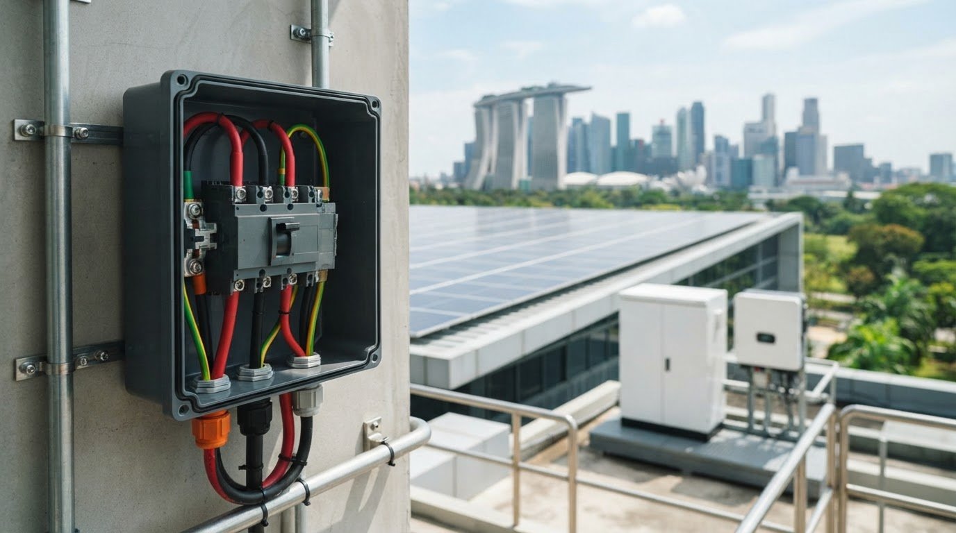
A breaker with the right current rating can still be the wrong choice for a solar circuit. DC circuit breakers for solar must match the circuit’s voltage, fault-current conditions, polarity requirements and installation position. An AC-rated breaker is not a substitute for a device designed to interrupt DC current.
The nameplate is a useful starting point, but selection depends on how the circuit is connected and what it needs to protect. A PV string, battery connection and inverter circuit can have different protection requirements. A breaker can interrupt specified overcurrent conditions, but it cannot compensate for incorrect wiring, system design or installation.
This guide explains where DC breakers fit in a PV system and how to assess voltage, current, polarity and interrupting ratings. It also covers placement and coordination across PV, battery and power-conversion circuits, including considerations for installations in Singapore. The key is to assess each circuit on its own, rather than apply one generic rating across the system.
Key Takeaways
- DC circuit breakers for solar must be selected for the specific circuit and fault conditions, not just the system’s nominal voltage.
- Keep circuit design inputs, such as expected current and fault conditions, separate from the values shown on a breaker’s nameplate.
- Use the system diagram and equipment documentation to assess protection and placement for PV-array, battery and inverter-side circuits.
- Distinguish overcurrent protection from circuit isolation when assessing a breaker’s role and limitations.
- Coordinate breakers with fuses, disconnects, surge protection and connected equipment as part of the complete protection plan.
What DC Circuit Breakers for Solar Protect, and What They Cannot Do
A DC circuit breaker is a protective switching device installed in a direct-current circuit. It is designed to open the circuit when current exceeds specified conditions, helping limit damage from overloads or short circuits. Some breakers can also be operated manually to interrupt a circuit, but this switching function is distinct from overcurrent protection. An isolator or disconnect may provide a dedicated means of isolation without providing overcurrent protection.
DC circuit breakers for solar are designed and rated for the direct-current conditions of a photovoltaic or storage circuit. AC breakers are not automatically suitable. Conventional AC current passes through zero during each cycle, which helps extinguish the arc when contacts open. DC lacks that recurring zero crossing, so the breaker must manage a sustained arc and interrupt current at the specified DC voltage and fault conditions. A general overview of the Circuit breaker explains the device’s switching and protective purpose, but suitability for a particular circuit depends on the breaker’s documentation.
How a DC breaker interrupts current
When breaker contacts separate under load or during a fault, an electrical arc can form between them. A DC-rated device is designed to control and extinguish that arc within its stated operating limits. Selection therefore requires more than matching a current value. Check that the breaker’s DC voltage rating, interrupting capacity, connection requirements and intended application suit the circuit. Do not infer DC suitability from an AC rating alone.
Where DC breakers fit in a photovoltaic system
A PV system may include module strings, a combiner, a charge controller, a battery and an inverter. These components connect through circuits with different current sources, operating conditions and potential fault paths. A breaker suitable for one circuit may not provide the required protection in another. Protection requirements depend on the circuit diagram, equipment instructions and system configuration.
For example, PV strings may feed a combiner before the DC output continues to conversion equipment. A battery circuit has the battery as its source, while an inverter-side DC connection serves power conversion. Assess each circuit against its own conditions rather than applying one breaker rating across the installation.
A breaker also has limitations. It does not correct undersized conductors, poor connections, incorrect polarity or unsuitable system design. Nor does it replace every fuse, disconnect, surge protection device or equipment-level safeguard. These components have different functions and must work as a coordinated arrangement. A review of solar circuit protection devices should consider each circuit’s role, the device assigned to protect it and the equipment it serves.
Which DC Breaker Ratings Matter in a Solar System?
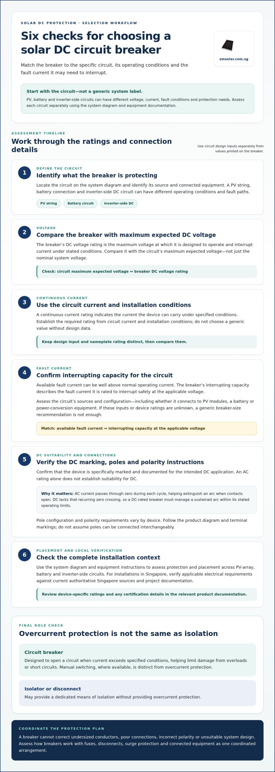
Selecting DC circuit breakers for solar means matching device ratings to the circuit’s operating conditions and the fault current it may need to interrupt. A nominal system label alone is not enough. PV, battery and inverter circuits can have different voltage and current profiles, so assess each against the design documents and the breaker’s markings and technical documentation.
Voltage, current, and interrupting capacity
Voltage rating is the maximum DC voltage at which the breaker is designed to operate and interrupt current under its stated conditions. Compare it with the circuit’s maximum expected voltage, not just its nominal voltage. Continuous current rating indicates the current the device can carry under specified conditions. Use circuit current and installation conditions to establish the required rating, rather than choosing a generic value without design data.
Interrupting capacity describes the fault current the breaker is rated to interrupt safely at the applicable voltage. Available fault current matters because a short circuit can expose the device to current well above normal operating levels. The assessment depends on the circuit, its sources and its configuration, including whether it connects to PV modules, a battery or power-conversion equipment. Avoid generic breaker-size recommendations when these inputs and the device ratings are unknown.
DC suitability, poles, and polarity
Confirm that the breaker is specifically marked and documented for the intended DC application. An AC rating alone does not establish suitability for a DC circuit. Pole configuration and polarity instructions also vary by device design. Some breakers require a defined connection arrangement to interrupt DC current as rated. Follow the product diagram and terminal markings rather than assuming poles can be connected interchangeably.
For an installation in Singapore, verify applicable electrical requirements against current authoritative Singapore sources and the project documentation. Check device-specific ratings and any certification details in the relevant product documentation. Do not infer compliance from a general DC marking alone.
Checklist: Compare the circuit’s maximum DC voltage, expected continuous current and available fault current with the breaker’s interrupting capacity, DC application marking, pole configuration and polarity instructions. Use the design documents and device documentation for this review.
Review solar circuit protection alongside the connected system equipment and circuit design.
How DC Breaker Requirements Differ Across Solar Circuit Locations
Breaker selection changes with the circuit’s source, connected equipment and fault conditions. A PV array, battery bank and inverter-side connection should not be treated as interchangeable, even when they are part of the same DC system. Use the circuit diagram and component documentation to determine protection requirements and device placement.
| Circuit location | Key considerations |
|---|---|
| PV strings and combiner | String layout, parallel connections, possible reverse current from other strings, array voltage and combiner design. |
| Battery circuit | Battery characteristics, connected conductors and equipment, available fault current, and the battery manufacturer’s protection instructions. |
| Inverter or charge-controller DC side | Equipment input limits, circuit configuration, specified protective-device requirements and the connection’s fault conditions. |
PV strings and combiner circuits
String configuration affects current flow during normal operation and under a fault. In a combiner, parallel strings may contribute reverse current toward a faulted string. The design must account for module and system configuration when determining whether and where overcurrent protection is required. Check applicable Singapore electrical requirements using current authoritative sources, and assess the array alongside the technical information for the monocrystalline solar panels used.
Battery and inverter DC circuits
A battery can supply fault current, so the assessment must account for its documentation, the circuit conductors and connected equipment. Lithium LiFePO4 battery specifications provide relevant context, but they do not replace system-level protection design. On the inverter or charge-controller side, follow the equipment instructions for DC connections and protective devices. The same arrangement will not suit every topology.
Keep device functions distinct. A breaker provides overcurrent protection when selected and installed for that purpose, and some designs also allow switching. A fuse interrupts current through its fusible element. A disconnect switch provides isolation according to its design and rating. These devices are not automatic substitutes for one another. DC circuit breakers for solar must be selected and positioned for the specific circuit, with the diagram and equipment documentation guiding the complete arrangement.
How to Assess and Specify a DC Circuit Breaker for Solar
Specify the breaker for the circuit it serves, rather than selecting a familiar rating from a product label. For DC circuit breakers for solar, design inputs describe the circuit and its operating or fault conditions. The breaker nameplate and technical documentation state the device’s limits. Both sets of information must align.
Build the circuit specification
- Identify the circuit. Mark its location and function on the system diagram, such as a PV string output, battery connection, charge-controller circuit or inverter DC input. Note the source and connected equipment.
- Record design inputs. Gather conductor details, system configuration, expected operating conditions and available fault-current information from approved design documents and equipment documentation. Keep these details separate from the breaker’s ratings.
- Define the protection requirement. Determine what the device is intended to protect and how it fits with other protective devices in the circuit. Do not assume the same arrangement applies to every string, battery or inverter topology.
- Compare device documentation. Check the breaker’s DC voltage and current ratings, interrupting capacity, pole arrangement, and any polarity or connection instructions against the design inputs. A nameplate value is a device limit, not proof that the breaker suits the circuit.
Review coordination and installation
Next, assess the breaker in relation to upstream and downstream protection. Review relevant fuse or breaker characteristics and the connected equipment’s instructions to confirm that the specified devices form a coordinated arrangement. Record assumptions and unresolved design inputs instead of substituting a generic breaker recommendation.
Installation conditions matter too. Follow the manufacturer’s guidance for enclosure, terminal connections, orientation and environmental conditions. Confirm that the selected device can be installed as documented and that the wiring and circuit arrangement match the system design.
For a project in Singapore, check the design against current applicable local electrical requirements using authoritative sources. Overseas code references or a product’s general DC marking do not confirm local compliance. Keep applicable requirements and device documentation with the specification for installation review.
Selection summary: The correct breaker depends on circuit topology, fault conditions, and documentation for connected equipment and the device itself. Final review should compare these design inputs with breaker nameplate values, manufacturer instructions and applicable Singapore requirements.
Review SM Solar’s solar circuit protection as part of a coordinated DC hardware specification.
Integrating Solar DC Circuit Breakers into a Complete Protection Plan
A breaker is one component in a wider protection arrangement. Define its role alongside the functions of fuses, disconnect switches, surge protection devices and connected equipment. These devices address different conditions and are not interchangeable. A breaker selected for overcurrent protection does not automatically provide surge protection, while a disconnect’s isolation function does not establish overcurrent protection.
Coordinate devices across the DC system
Start with the system circuit diagram. Map each protective device to the circuit it serves and the equipment interfaces around it, such as PV strings, combiner circuits, batteries, charge controllers and inverters. Then check the design requirements and documentation for each device and connected component. This can help identify gaps, duplication and incompatible assumptions in the protection plan.
Coordination involves more than placing devices in sequence. Each device must suit its circuit conditions and operate within its documented limits. Review conductor and equipment requirements, device ratings, terminal arrangements and manufacturer installation instructions together. Installation should follow the approved design, applicable requirements and device documentation, with qualified personnel carrying out the work.
For example, do not replace a fuse specified for a particular equipment connection with a breaker solely because both interrupt current. A disconnect switch may provide a means of isolation, while a surge protection device addresses transient overvoltage conditions. The complete plan assigns each device a defined function and checks that its ratings and installation match that role.
From component specification to system integration
System integration connects the selected breaker with the PV, battery and conversion equipment it serves. This means checking the circuit diagram, equipment interfaces and manufacturer requirements as a coordinated set, rather than treating the breaker as a standalone purchase. The final protection arrangement must follow the project design and technical documentation for all relevant devices.
SM Solar distributes solar circuit protection devices through a wholesale portfolio of DC-related solar products. The company also provides system integration, installation and after-sales maintenance. These capabilities connect component selection with wider system and installation requirements, while device suitability remains based on circuit conditions and product documentation.
Keep the circuit diagram, device documentation and installation requirements aligned through procurement and implementation. Together, they provide a clear reference for reviewing how protection devices connect with the rest of the DC hardware.
View SM Solar’s solar circuit protection range as part of a coordinated DC hardware plan.
Specify Protection by Circuit, Then Review the Complete System
Reliable breaker selection starts with the circuit, not a generic rating. Match voltage, current, interrupting capacity, DC suitability, pole arrangement and polarity to the design inputs and device documentation. Then review how the breaker coordinates with fuses, disconnects, surge protection and connected equipment. Each device has a defined role, and the complete arrangement must fit the system topology and applicable requirements.
These checks make DC circuit breakers for solar part of a coordinated protection plan rather than an isolated hardware choice. SM Solar distributes solar circuit protection within its DC-related product portfolio. The company also provides system integration, installation and after-sales maintenance, connecting protection hardware with broader system requirements.
Explore SM Solar’s solar circuit protection range and get in touch to discuss your DC hardware specification. Aligning the design inputs and equipment documentation helps you move forward with a clearer, coordinated protection plan.
Frequently Asked Questions
What is a DC circuit breaker for solar?
A DC circuit breaker for solar is a protective switching device designed to carry and interrupt current in a direct-current circuit under specified conditions. It can open the circuit when current exceeds its protection limits, and some designs also provide manual switching. Its voltage, current, interrupting capacity and DC application must match the circuit. It does not replace correct system design or other protection devices with separate functions.
Can I use an AC circuit breaker in a solar DC circuit?
No. An AC rating alone does not establish suitability for a solar DC circuit. DC arcs can persist because the current does not pass through a natural zero crossing as AC does. Use a breaker whose markings and technical documentation specify the required DC application, connection arrangement and ratings. An AC breaker used outside its documented DC capability may fail to interrupt a fault safely. Confirm suitability against the circuit design.
How do I size a DC circuit breaker for a solar panel system?
Size the breaker from the circuit’s design conditions, not from a generic rule or the system’s nominal description. Identify the circuit, then use approved design and equipment documentation to establish expected current, maximum DC voltage and available fault current. Compare those inputs with the breaker’s continuous-current rating and interrupting capacity. Also check DC suitability, pole configuration, polarity instructions and installation conditions before specifying a device.
Where should DC circuit breakers be installed in a solar system?
Install breakers only at positions identified by the system design and applicable requirements. PV strings, combiner circuits, battery connections, charge-controller circuits and inverter DC connections have different sources and fault conditions, so their placement is not interchangeable. Follow the circuit diagram and each connected device’s documentation to determine which circuits require protection and where devices belong. Review enclosure, terminal and orientation instructions as part of the installation specification.
Do solar batteries need a separate DC circuit breaker?
A battery circuit needs protection designed for its source, conductors, connected equipment and fault conditions, but the required arrangement depends on the system design and equipment documentation. Do not assume that a PV-side breaker also protects the battery connection, or that every system uses an identical device layout. Check the battery and inverter or charge-controller instructions, then confirm the selected protection and placement against the circuit diagram.
What happens if a DC circuit breaker has the wrong voltage rating?
A breaker with an inadequate DC voltage rating may be unable to interrupt current safely at the circuit’s operating or fault voltage. The arc may not extinguish as intended, creating a risk of device failure and damage to connected equipment. A rating that appears close to the nominal system voltage is not enough. Compare the circuit’s maximum expected voltage with the breaker’s DC rating and product documentation before installation.
Leave a Reply