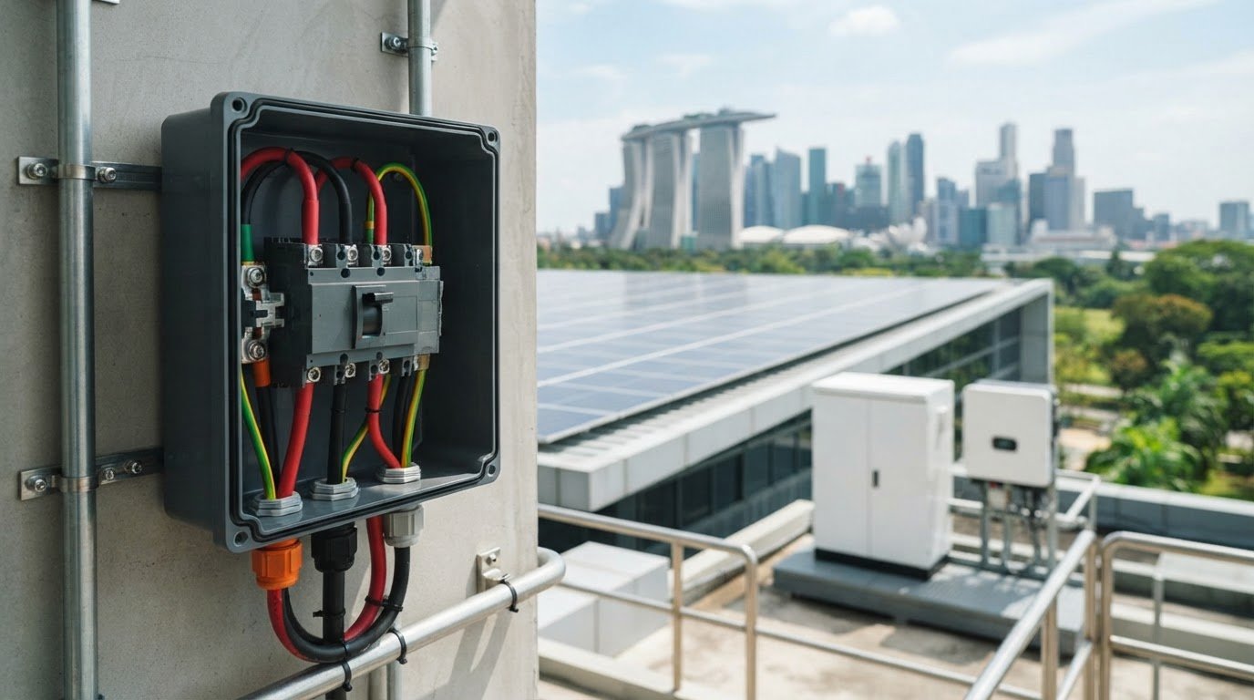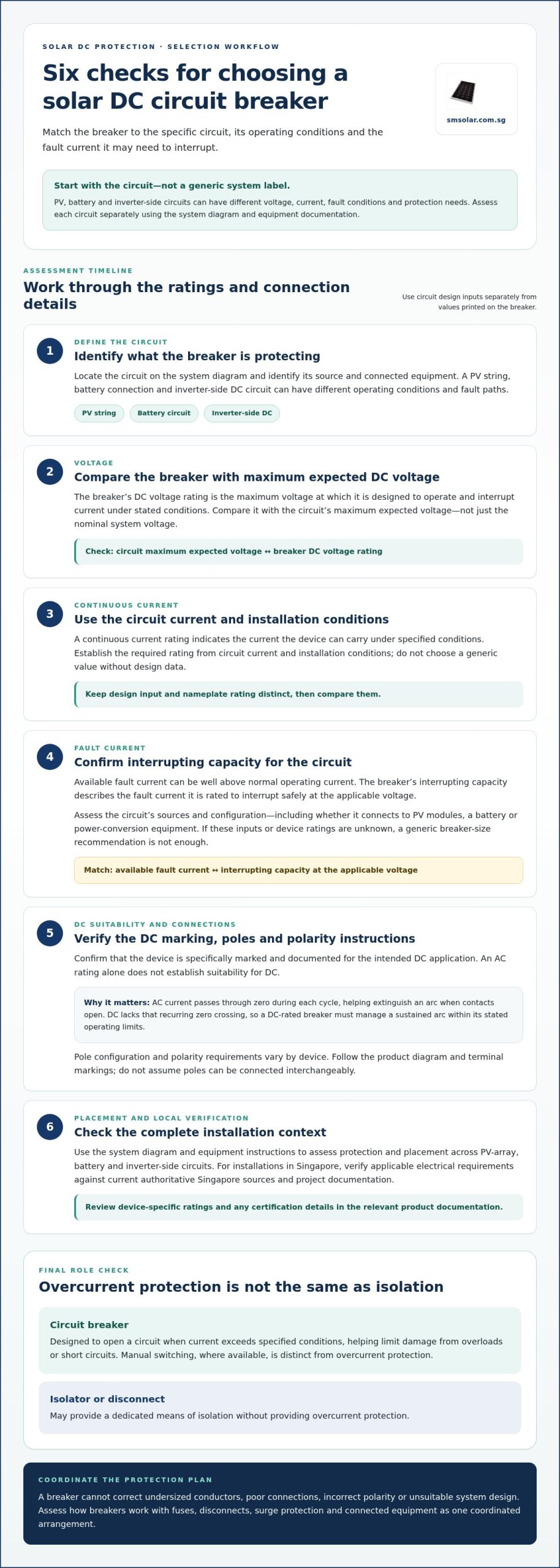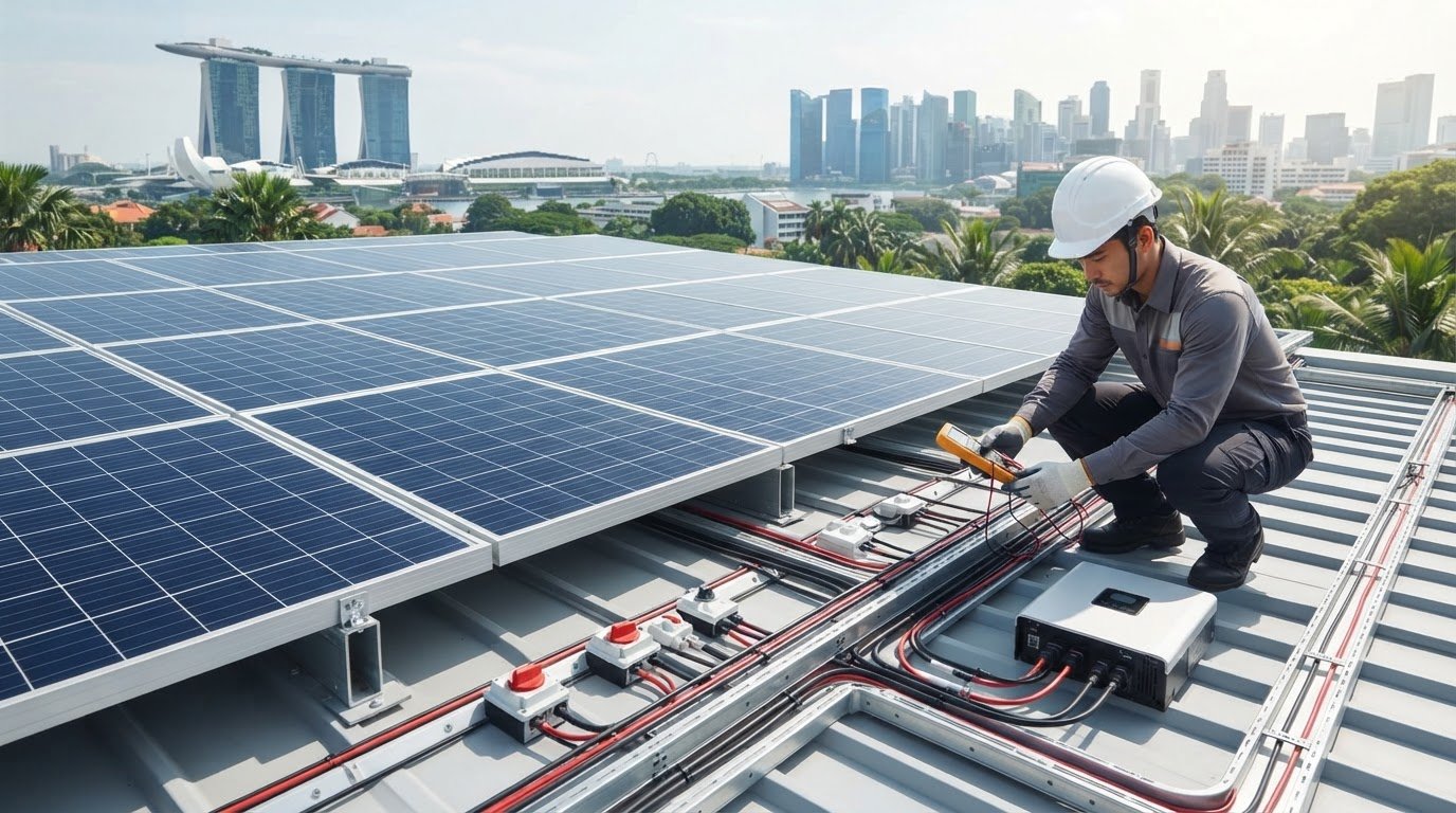
A string configuration that looks correct on paper can still exceed an inverter’s voltage limit under the project’s operating conditions. This solar panel wiring guide for installers provides a repeatable way to check a design before wiring begins. The right choice depends on more than the number of modules: module electrical data, inverter input limits, temperature effects, protection and cable selection all matter.
Series, parallel and combined arrangements each involve practical trade-offs. A structured review helps identify mismatches early and carry design decisions through to consistent field checks and records.
This guide covers the workflow from reviewing module and inverter documentation to comparing string options, checking voltage and current limits, and specifying compatible wiring and protection components. It also outlines field verification and documentation points for a safer, more traceable installation. For Singapore PV systems, assess the design against applicable requirements, including SS 638:2018 and its Section 712 provisions. The result is a practical framework for planning project-specific DC component sets.
Key Takeaways
- Trace the DC path from PV modules through disconnects and protection to the inverter inputs before selecting components.
- Compare series, parallel and combined stringing by voltage, current and MPPT implications.
- Use this solar panel wiring guide for installers to review module data, inverter limits, shading and cable routes in a consistent sequence.
- Base string calculations and conductor choices on project-specific data and the relevant manufacturers’ documentation.
- Plan field checks and installation records alongside the design, and verify applicable Singapore electrical, fire-safety and inspection requirements against authoritative sources.
Solar Panel Wiring for Installers: What the Electrical Layout Must Connect
PV wiring connects photovoltaic modules, strings, conductors and system equipment. A PV string is a group of modules connected electrically in series. The complete array is the collection of one or more strings feeding the system. A clear layout shows both how the modules form strings and how each string connects to the conversion equipment.
Start at the modules and trace the DC path through string conductors and connectors, then through any specified disconnects or protection devices to the inverter inputs. The equipment order depends on the system design and applicable requirements. Show each device in its intended position rather than treating the path as a generic template. The Solar Panel Basics reference provides background on how modules generate electrical output; wiring design translates that output into compatible system connections.
Which components belong in a solar panel wiring layout?
Show the modules, string boundaries, positive and negative conductors, connector interfaces, protection devices and inverter inputs. If the design includes a charge controller and battery, include the controller’s PV-side terminals and the relevant battery-side connections. Label equipment clearly so the drawing can be checked against the components selected for installation.
Keep the PV-side DC boundary distinct from the inverter-side AC boundary. The inverter converts DC power for the AC system, but this section covers only the DC wiring path and its connection to the inverter inputs, not AC installation procedures.
What information should installers collect before designing?
Build the design from project-specific documents and site information, not assumptions based on a familiar module or inverter. Record the applicable jurisdiction and project scope because electrical, fire-safety and inspection requirements can vary.
- Module documentation: Record electrical ratings, open-circuit voltage, short-circuit current, operating values, temperature coefficients and stated temperature limits. Use the manufacturer’s data to assess how output may change across the project’s operating temperatures.
- Inverter or controller documentation: Capture input voltage and current ranges, MPPT input allocation, connection limits and permitted configurations. Note which input is assigned to each planned string.
- Site information: Map module positions, shading differences, equipment locations and cable routes. Record route length and installation constraints that could affect conductor planning.
For Singapore projects, include SS 638:2018 and the PV provisions in Section 712 in the standards review, while confirming current applicability against authoritative requirements for the project. Check equipment limits against the documentation for the exact models selected. These inputs establish the design basis before string configuration, conductor sizing and field checks begin.
How Series and Parallel Solar Panel Wiring Change Array Behaviour
Configuration determines how module voltage and current reach each inverter or controller input. In series, module voltages add while string current remains approximately at the level of one module. In parallel, branch currents add while voltage remains approximately at the level of one branch. These relationships help with an initial comparison, but the equipment’s permitted input range and operating limits determine whether an arrangement is suitable.
When is series wiring a suitable configuration?
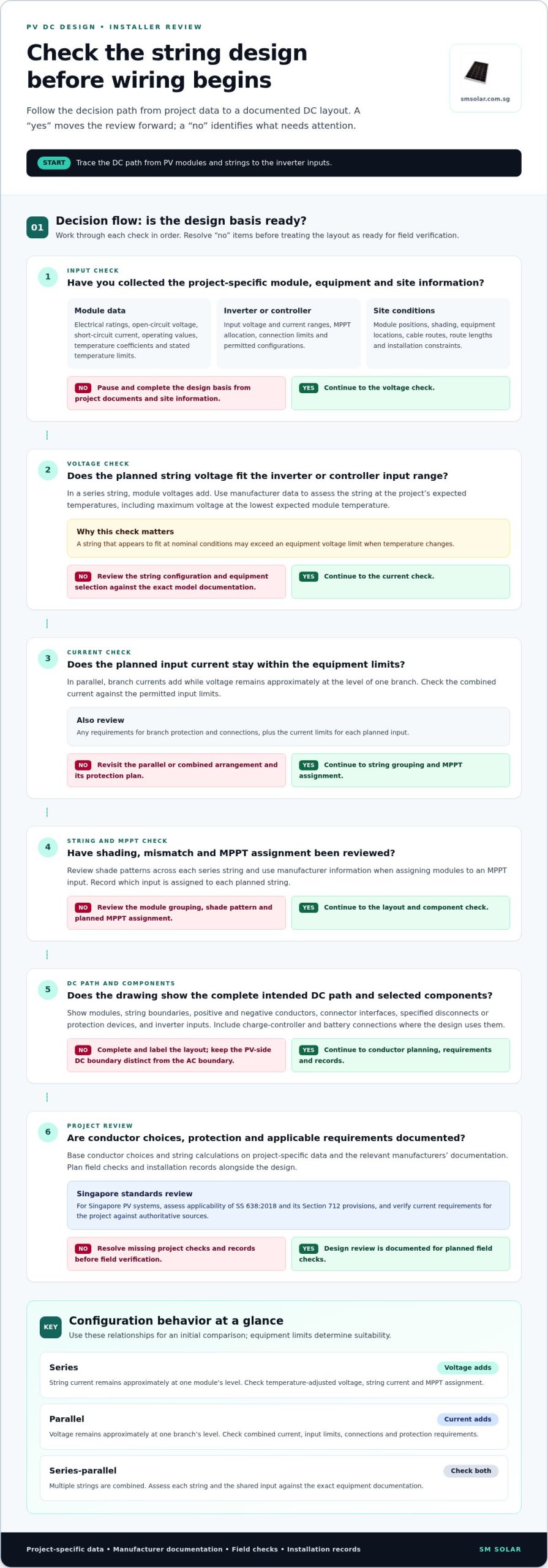
Series wiring connects modules positive-to-negative to form a string. Each module adds to the combined operating voltage, so check the string voltage against the inverter or controller input range. Also assess maximum voltage at the project’s lowest expected module temperature using manufacturer data. A string that fits at nominal conditions may exceed an equipment limit when temperature changes.
Current through a series string is governed by its module design, rather than added across the modules. Shading or electrical mismatch can affect string output, depending on module characteristics and system design. Review shade patterns across the string and the manufacturer’s information before assigning modules to an MPPT input.
When should parallel or series-parallel wiring be evaluated?
Parallel branches combine current at a shared voltage. Compare the total input current with the inverter or controller’s permitted limits, and check any requirements for branch protection and connections. In a series-parallel arrangement, modules form multiple strings and those strings are combined. This offers another way to meet voltage and current needs, but assess each string and shared input against the exact equipment documentation.
Series
Electrical effect: Module voltages add; string current remains approximately at one module’s level.
Design check: Confirm temperature-adjusted string voltage fits the input range, then verify string current and MPPT assignment.
Typical trade-off: Higher voltage per string, with output potentially affected by shading or mismatch within that string.
Parallel
Electrical effect: Branch currents add; voltage remains approximately at one branch’s level.
Design check: Confirm combined current, input limits and required protection for the arrangement.
Typical trade-off: More current at the input and additional branch connections to plan.
Series-parallel
Electrical effect: Series strings are combined in parallel, increasing both array voltage and current relative to a single module.
Design check: Verify each string’s voltage and current, total input limits and permitted MPPT configuration.
Typical trade-off: More configuration flexibility, with more interaction between string design, protection and input allocation.
Compare configurations against the actual modules, inverter or controller, site shading and cable routes. No arrangement is universally best. For project-specific DC component planning, solar panels, controllers and circuit protection can be considered as part of the same equipment set.
Compare Solar Panel String Options Against Modules, MPPTs and Site Conditions
A string configuration is viable only when it fits the module ratings, inverter or controller inputs, MPPT allocation and physical site layout together. Use a decision matrix to eliminate options that breach an equipment limit or cannot be routed practically. Screen configurations before detailed conductor selection so time is not spent sizing wiring for an arrangement the equipment cannot accept.
Start with the exact module model and its technical documentation. The monocrystalline solar panels technical overview provides context on module data; final design values must still come from the relevant manufacturer documentation. General series and parallel principles explain electrical behaviour, but they do not confirm that different module models or string combinations are approved for a specific inverter.
How do module and inverter limits narrow configuration choices?
Compare module operating voltage and current, open-circuit voltage and short-circuit current with the inverter or controller’s input range and limits. Assess maximum string voltage at the relevant temperature conditions using the documented calculation method and manufacturer data. Then check the number and allocation of MPPT inputs, including any instructions for strings connected to a shared tracker.
Rule out a configuration that exceeds an input voltage or current limit before selecting conductors. Similarly, a proposed string length outside the equipment’s permitted operating range cannot be made suitable by changing the cable. Keep manufacturer-approved module combinations distinct from general stringing principles.
How do shading and cable routes affect the comparison?
Map shade exposure by module location and planned string rather than treating the whole installation area as uniform. Where exposure differs, assess the effect on the proposed string grouping and MPPT assignment against the equipment documentation. Mark conductor routes, routing conditions and access constraints as well. A layout may be electrically compatible but still need revision if the route is impractical to install or inspect.
Module limits: Confirm operating values and temperature-related voltage against manufacturer data. Reject string options that exceed documented limits.
Inverter or controller inputs: Compare voltage and current ranges with the proposed configuration. Record the input limits that eliminate an option.
MPPT assignment: Map each string to its intended tracker and follow the equipment’s configuration instructions.
Shading: Note which modules and strings have differing exposure. Assess the effect before grouping them on an input.
Route constraints: Mark cable paths, access and installation conditions. Carry these details into conductor design.
For example, if a proposed string exceeds the documented maximum input voltage under the applicable temperature condition, remove it from consideration before comparing cable routes. Record the failed limit, data source and assumptions. This makes the decision reviewable and keeps the solar panel wiring guide for installers grounded in project evidence rather than a preferred configuration.
A Solar Panel Wiring Workflow for String Sizing and Field Installation
Use a controlled sequence from source data to as-built records. This solar panel wiring guide for installers links string selection, conductor specification and field verification, with calculations based on project inputs and applicable manufacturer documentation.
- Collect project documents. Gather module, inverter or controller datasheets, equipment instructions, site drawings and applicable project requirements. Record module electrical values, temperature-related limits, input ranges, MPPT allocation and installation conditions.
- Model candidate strings. Map proposed modules to strings and intended inputs. Include module locations and shading differences. Use the actual equipment models and the project’s documented operating conditions, not generic assumptions.
- Verify electrical limits. Check string voltage and current against inverter or controller limits, including temperature effects on voltage. Review permitted string and MPPT configurations in the equipment instructions. Remove options that fall outside a documented limit.
- Specify conductors and protection. Assess conductor ampacity and voltage drop using applicable design rules, route length and installation conditions. Select compatible connectors and protection components based on equipment documentation and project requirements. The solar circuit protection devices guide provides additional context for protection-device design.
- Install to the approved layout. Follow planned routes and support methods. Identify conductors and protect them from physical damage in accordance with the design and applicable requirements. Confirm connector compatibility and engagement using the connector manufacturer’s instructions. Avoid mixing connector types unless the manufacturers permit that combination.
- Inspect, test and record. Complete the checks and electrical tests required by the project procedure. Record the test method, instrument identification, results, date and responsible sign-offs. Update drawings to show installed string assignments, equipment inputs and approved field changes.
How should installers verify string and conductor sizing?
Keep calculations traceable. Show the source values, calculation method, temperature assumptions, route conditions and applicable design rules. Conductor ampacity depends on installation conditions, while voltage drop depends on the circuit and route. Avoid applying a universal cable size. Document the selected conductor against the specific installation and equipment requirements.
Which field checks support a reliable wiring handover?
Inspect routing, support, connector engagement, polarity identification and cable protection against the approved layout. Follow project procedures for electrical testing; a visual inspection does not replace required measurements. If a string connection or route changes in the field, record the change and verify the revised arrangement before handover.
A complete record links the design to the installed system: datasheets, string calculations, equipment configuration, protection selection, inspection notes, test results and updated as-built drawings. For project-specific DC components, explore solar circuit protection and related hardware for your system design.
Singapore Compliance, Project Records and Solar Wiring Component Planning
Electrical design principles such as checking voltage, current, temperature effects and equipment compatibility apply broadly. Approval, inspection, fire-safety and installation rules depend on jurisdiction and project scope. Separate these two layers: document the engineering basis, then establish which Singapore requirements apply to the specific project.
How should installers handle code and standards references?
Do not apply US NEC references by default to Singapore projects. The identified Singapore electrical installation code of practice is SS 638:2018, including Section 712 for PV systems. Confirm the applicable edition, project requirements and approval processes against authoritative sources before work proceeds. Manufacturer instructions are equipment-specific requirements and should be distinguished from regulatory obligations.
For fire-safety and lightning-protection considerations, establish which requirements apply to the project and verify them against relevant authorities and current standards documents. SS 555:2018 is the identified lightning protection standard. Requirements and review responsibilities may depend on system scope, so do not treat a general reference as a complete approval checklist.
How can component planning support a traceable design?
Translate each design requirement into a component category and specification reference. Match module data to the selected inverter or charge controller inputs; include batteries where the system design requires them; and document protection-device selection against the circuit design and applicable equipment instructions. Record the manufacturer, model and relevant datasheet revision so procurement can be checked against the approved design.
- Equipment records: Keep module, inverter, controller and battery documentation with the design file.
- Protection records: Link each selected protection device to its intended circuit and design basis.
- Drawing control: Maintain the wiring schedule, single-line diagram and revision history together.
- Handover evidence: File inspection and test records against the installed configuration, including approved changes.
This traceability reduces ambiguity between the design, purchased hardware and installed arrangement. If a component changes, review the affected calculations, input compatibility and drawings rather than updating the procurement list alone.
SM Solar supplies wholesale solar hardware, including monocrystalline solar panels, charge controllers, batteries and solar circuit protection. Its system integration capabilities support the assembly of project-specific DC component sets, alongside the project’s engineering and regulatory review. Keep procurement aligned with approved specifications; the solar energy equipment supplier buyer’s guide provides further context for organizing that process.
Close the project file with applicable standards references, approval records, the final equipment schedule, test evidence and as-built drawings. Verify current Singapore electrical, fire-safety and inspection requirements through authoritative sources for each project. This keeps the compliance basis clear and makes later review more reliable.
Put the Wiring Plan to Work
Make the next project easier to review by turning the design basis into a reusable project checklist. Set out the required source documents, calculation references, equipment selections, inspection points and handover records in one controlled package. Update it for each site and equipment combination instead of carrying assumptions forward. This helps keep design decisions visible from initial specification through field verification.
Use this solar panel wiring guide for installers as a reference when building a project-specific component schedule. Match each selected item to the approved design and manufacturer documentation, then keep procurement records aligned with the final wiring plan.
Review SM Solar’s solar hardware range to plan components for your next PV project. A clear design basis and well-organised equipment schedule give your team a practical starting point for the work ahead.
Frequently Asked Questions
How do installers calculate the maximum number of solar panels in a string?
Use the module’s open-circuit voltage, adjusted for the lowest design temperature, to calculate the maximum series count allowed by the inverter’s maximum DC input voltage. Then check that the resulting operating voltage also fits the inverter’s MPPT range. Apply the manufacturer’s calculation method and temperature data. This gives an equipment-based upper limit, not a recommended string length; current limits and project requirements may reduce it further.
What happens if a PV string exceeds the inverter’s maximum input voltage?
An overvoltage string can cause the inverter to trip or fail to operate, and may damage its input circuitry. The actual response depends on the equipment, but built-in protection should not be treated as permission to exceed a stated limit. Recheck the string calculation using the module’s temperature-adjusted open-circuit voltage and the inverter documentation. Do not connect the string until the design is within the specified maximum.
Can solar panels with different electrical ratings be connected in the same string?
Only if the equipment manufacturers’ instructions and the project design permit that combination. In a series string, current is shared, so modules with different current characteristics can constrain the string’s operating behaviour. Differences in voltage can also affect the usable operating range. Compare the exact module datasheets, not just nominal wattage, and document the basis for mixing models. If compatibility cannot be established, keep the modules in separate, appropriately assigned strings.
Are MC4-compatible connectors from different manufacturers interchangeable?
No. A connector described as MC4-compatible is not automatically approved for mating with every connector using that interface. Differences in construction or contact design can affect connection quality and safety. Use connector combinations that the respective manufacturers explicitly permit, and follow their assembly instructions and tooling requirements. Record connector make and model in the installation schedule so replacements or field changes do not introduce unverified pairings.
How should installers assess voltage drop in solar panel wiring?
Calculate voltage drop using the circuit current, conductor material and cross-sectional area, operating temperature, and the full current path length. For a DC circuit, account for both outgoing and return conductors. Compare the calculated drop with the project’s design criteria and applicable requirements, then adjust conductor selection or routing if needed. Keep the calculation inputs and method on file; a cable size alone does not demonstrate acceptable voltage drop.
What records should be included in a solar installation wiring handover?
Include the final wiring diagram and string schedule, equipment datasheets, string and conductor calculations, protection-device selections, inspection notes, test methods and results, instrument details, sign-offs, and a revision history. Add approved field changes and identify the final equipment models and MPPT assignments. A complete handover lets a reviewer trace each installed connection back to its design basis and helps future maintenance teams understand what was built.
Does the NEC apply to solar panel wiring projects in Singapore?
The NEC is a US electrical code and should not be assumed to govern a Singapore project. Identify the Singapore requirements and approval processes applicable to the project scope; SS 638:2018, including Section 712 for PV systems, is the relevant electrical installation standard identified for Singapore. Confirm current requirements and editions with authoritative sources before design or publication. Manufacturer instructions remain essential for equipment-specific limits, but they are not a substitute for local requirements.