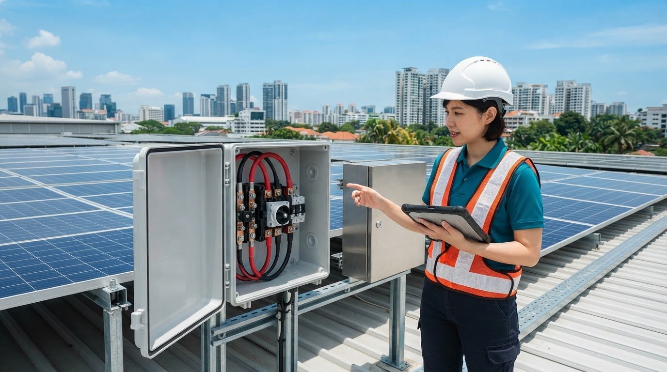
What if a switch can isolate a PV circuit but isn’t rated for its voltage, current or switching duty? That mismatch is easy to miss when comparing DC disconnect switches solar projects require. A disconnect’s role differs from overcurrent protection, and its suitability depends on the circuit design and the point where isolation is needed.
Questions about placement, ratings and applicable code guidance are common. This checklist explains what a solar DC disconnect switch does, how to compare its electrical and switching ratings with the circuit, and how to review its position in the PV system.
It also distinguishes isolation from circuit protection and outlines design details to verify against current Singapore requirements, including applicable provisions of SS 638 and SS 650. Use it as a framework for reviewing disconnect switches as part of a coordinated PV hardware specification, rather than assuming overseas guidance applies unchanged.
Key Takeaways
- Use a DC disconnect to isolate a PV circuit for service or emergency shutdown. Don’t treat it as a substitute for overcurrent protection.
- For DC disconnect switches solar systems require, compare the switch’s voltage, current and switching ratings with the circuit design values.
- Assess the circuit location and equipment access needs when reviewing disconnect placement.
- Use a consistent checklist to record design inputs, device selection, installation details and commissioning results.
- Verify applicable Singapore requirements for the specific PV installation rather than applying overseas guidance without review.
What Do Solar DC Disconnect Switches Do in a PV System?
A DC disconnect switch opens a selected direct-current circuit to provide an isolation point from downstream equipment. In a photovoltaic system, that point can support maintenance or fault response. Opening the switch doesn’t automatically de-energise every component: illuminated modules can continue producing DC voltage on the array side. Safe work depends on the system’s isolation plan and on identifying equipment that remains energised.
For DC disconnect switches solar systems use, the function is isolation, not a general guarantee that a circuit is safe to touch. The role of a disconnector in electrical systems is described in What is a Disconnector? In a PV design, consider the switch alongside the circuit configuration, protection devices, inverter instructions and access for the people who may need to operate it.
Where the DC disconnect fits in a solar array
A typical DC path starts at PV modules, which may be wired into string circuits. Depending on the design, strings may connect through combiner equipment before reaching the inverter, where DC power is converted to AC. A PV-side disconnect interrupts a designated part of the DC path. An AC disconnect sits on the inverter’s AC output side and serves a different circuit.
There isn’t one universal arrangement. A system may have isolation points at different equipment or circuit boundaries, depending on its configuration and applicable requirements. Use the system drawing and inverter documentation to identify what each switch isolates. Clear labels and unobstructed access help maintenance personnel find the correct point, while the isolation procedure should identify any sections that remain energised.
- Modules and strings: DC generation begins here, and conductors may remain energised in daylight.
- Combiner equipment: Where used, it brings multiple strings together and may include circuit protection.
- Inverter: Receives DC input and supplies converted AC power to the downstream system.
Review placement as part of the complete circuit path, not from a generic diagram alone. A switch on the PV side doesn’t replace the AC isolation point. Operating one switch also doesn’t necessarily isolate other strings, batteries or equipment connected elsewhere in the system.
Disconnect switch versus DC circuit breaker
A disconnect switch is selected primarily to open and isolate a circuit under its specified operating conditions. A DC circuit breaker provides overcurrent protection when designed and rated for that duty. Some devices may perform more than one function, but their marked ratings and documentation determine their capabilities. Don’t assume a disconnect will interrupt fault current or that any breaker provides every required isolation function.
Selection must account for the DC circuit, not just a familiar AC component or handle style. DC arcs behave differently from AC arcs, so the device must be rated for the relevant DC application. Keep isolation and overcurrent protection separate in the design review. For breaker-specific selection considerations, see the DC circuit breaker selection and safety guide.
Which DC Disconnect Ratings Must Match the Solar Circuit?
A switch’s headline voltage and current values are only a starting point. Selection depends on the circuit it will isolate, conditions at the installation location and the device’s specified DC switching duty. Record the design inputs first, then compare them with the manufacturer’s datasheet and installation instructions.
Keep normal operating values separate from maximum design values. Array operating voltage and current describe expected conditions, but they may not represent the worst case used for equipment selection. Design calculations may account for module characteristics, string configuration, temperature effects and conductor arrangement. Follow the method required by the project design and current Singapore requirements, rather than applying a sizing rule from another jurisdiction. SEIA’s Solar Industry Codes and Standards resource offers broader industry context, but it doesn’t replace local requirements.
Voltage, current, and switching capacity
Check that the disconnect’s rated DC voltage is suitable for the circuit’s maximum design voltage. A nominal system label alone may not capture the maximum voltage under relevant conditions. Compare the documented design value with the device rating, following the manufacturer’s specified arrangement and limits.
Review current in the same way. Don’t match a switch to a typical operating-current reading without checking the circuit design and applicable derating factors. Confirm the rating for the intended switching duty, including whether the device is designed to make or break the relevant DC load. A rating for one DC configuration may not apply to another.
- Voltage: Compare the marked DC rating with the calculated maximum circuit voltage.
- Current: Use the design current and applicable correction or derating factors, not just expected operating current.
- Switching duty: Verify the manufacturer’s stated DC application and operating limits.
Enclosure and installation conditions
Electrical ratings aren’t the only consideration. Assess whether the enclosure and mounting location suit the actual exposure, including moisture, dust, direct sunlight, ambient temperature and ventilation. Match the ingress-protection level to site conditions and relevant installation requirements instead of choosing one by habit.
Check the physical connections too. Confirm compatibility with conductor material and size, terminal capacity, tightening instructions, cable entry and required clearances. Review polarity markings and the wiring diagram, especially if the device uses multiple poles or a specific pole arrangement. The number of poles must suit the circuit configuration and intended isolation. Incorrect connections can undermine an otherwise suitable rating.
Keep a record of the design voltage, design current, circuit configuration, conductor details, environmental conditions, device ratings and manufacturer instructions. Resolve mismatches before procurement or installation. For current Singapore projects, verify applicable local requirements and their editions through the project documentation and qualified design process. Overseas guidance does not automatically transfer. Coordinating solar circuit-protection hardware with the wider PV specification helps align component selection with the system design.
How Does a DC Disconnect Compare With Other Solar Protection Devices?
PV systems use devices that may look similar on a single-line diagram but serve different functions. A disconnect provides a means of isolation; a circuit breaker may interrupt overcurrent; an AC disconnect isolates an AC circuit; and a combiner box brings PV strings together. The equipment and coordination depend on the system design, equipment documentation and applicable requirements in Singapore.
| Component | Typical circuit location | Primary function | Protection role |
|---|---|---|---|
| DC disconnect | PV DC circuit, at a designed isolation point | Open and isolate a DC circuit for service or other specified operation | Isolation; don’t assume it provides overcurrent protection |
| DC circuit breaker | DC circuit, as specified in the system design | Interrupt current under defined operating conditions | Provides overcurrent protection when designed and rated for that function |
| AC disconnect | Inverter AC output or another designated AC circuit | Isolate the AC side of equipment | Isolation on an AC circuit; not a substitute for a DC-rated device |
| Combiner box | Where multiple PV strings are brought together | Combine string circuits into an output circuit | May contain protective or isolation devices, depending on its design |
DC disconnects and overcurrent protection
Separate the isolation task from the overcurrent task during design review. A switch handle that opens a circuit doesn’t show, by itself, that the device will respond to overload or fault current. Likewise, a breaker’s protective function doesn’t establish that it meets every required isolation arrangement. Check the device markings, ratings and manufacturer documentation, then confirm each function against the circuit design. Don’t treat components as interchangeable without design evidence.
For a broader view of how protective devices fit together, consult this solar circuit protection devices guide. The DOE Solar Codes and Standards resource provides general context on codes and standards for solar systems. It doesn’t replace checking current Singapore requirements for a local project.
Disconnects and solar combiner boxes
A combiner box is an assembly point, not another name for a disconnect. It collects multiple PV string circuits where the system configuration calls for it. The enclosure may include string-level protective devices, an isolation device or other components, depending on the assembly and design. Identify the actual components and the conductors each one affects.
For example, a disconnect associated with a combiner assembly may isolate a defined output, while string protective devices serve different circuit functions. Don’t assume that opening one component isolates every string or every connected energy source. Review the single-line diagram and equipment documentation together. This solar combiner box components guide covers assembly roles in more detail.
Assess DC disconnect switches solar systems require as part of coordinated hardware selection, not as standalone components. Match each device to its circuit, function and rating, then confirm the arrangement against the project design and current applicable requirements.
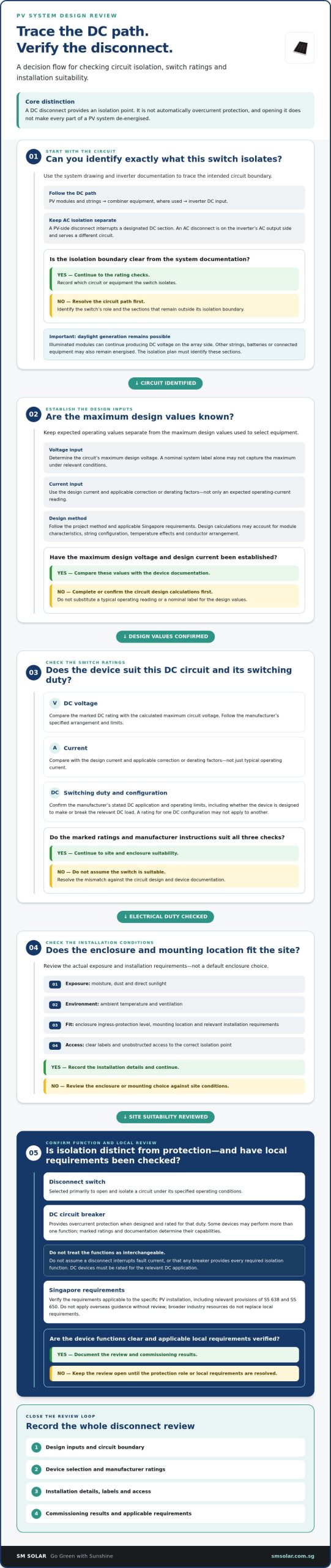
Solar DC Disconnect Switch Checklist: From Design Review to Commissioning
Review the disconnect across four stages: design inputs, device specification, installation and verification. This keeps selection tied to the PV circuit and its documentation rather than relying on a headline rating alone. For DC disconnect switches solar projects use, record the basis for each decision so it can be traced through procurement, installation and handover.
Before specifying or purchasing the switch
Start with the approved PV array and inverter documentation. Use the single-line diagram and equipment instructions to identify the circuit the switch must isolate, its location in the DC path and any connected sources relevant to isolation. Record the design values and configuration before comparing devices.
- Design inputs: Capture maximum design voltage, operating current, string or array configuration, and the applicable calculation assumptions.
- Circuit details: Note conductor material and size, polarity, number of poles, terminal requirements, and protective devices that must coordinate with the switch.
- Device specification: Compare DC voltage and current ratings with the design values. Confirm the manufacturer’s stated switching duty and operating limits for the intended circuit.
- Installation environment: Document the mounting location, exposure to moisture, dust and temperature, enclosure needs, cable entry and required clearances.
Separate normal operating readings from maximum design values. Use the project’s applicable calculations and correction factors. Don’t select a switch based solely on a typical production reading. Keep the datasheet, wiring diagram and inverter instructions with the selection record. Resolve any unclear rating, terminal detail or intended switching function through the project’s technical review before procurement.
Installation and handover checks
At installation, compare the actual device and wiring with the approved design and manufacturer instructions, and record any approved change. Check that the switch is positioned for its intended isolation function and can be reached without moving equipment or encountering avoidable obstructions.
- Verify device identification, polarity markings, labels and circuit references against the drawings.
- Confirm conductor and terminal compatibility, follow the specified termination method, and maintain required clearances.
- Inspect the enclosure, cable entries and mounting for suitability at the installed location.
- Document the isolation procedure, including which PV sections or other sources may remain energised.
- Record applicable commissioning checks, results, drawing updates and the responsible qualified personnel.
Commissioning scope and acceptance criteria must follow the project design, equipment documentation and current Singapore requirements. Verify the applicable code provisions and standard editions for the installation. Don’t transfer foreign code guidance without checking its local relevance. A complete handover record should help future maintenance personnel identify the correct isolation point and understand its limits.
For coordinated solar hardware and circuit-protection requirements, review SM Solar’s solar products alongside the PV system specification.
How SM Solar Supports Solar DC Protection Hardware Requirements
Disconnect selection is one part of a wider PV hardware specification. The switch must correspond to the circuit it isolates and coordinate with the system’s other DC equipment. Review the complete design rather than treating one component’s rating as a substitute for the array, storage or inverter documentation.
Specify disconnect hardware as part of a complete PV design
In a PV system, modules, charge controllers, batteries and inverter architecture shape the DC circuits and their isolation needs. A system with storage, for example, has different equipment paths to account for than a grid-connected array without a battery. Map those paths using the project’s diagrams and equipment documents before specifying protection hardware.
SM Solar is a wholesale distributor of solar products, including circuit protection devices and other DC-related products. Its product range supports solar hardware projects where components need to be considered as part of a coordinated specification. The right switch and protection arrangement depend on the documented project requirements, manufacturer information and current Singapore requirements.
For DC disconnect switches solar projects require, keep the switch’s isolation role distinct from the functions of breakers and other protective devices. A coordinated review considers the relevant circuit boundaries, system configuration and equipment interfaces together. SM Solar also provides system integration, connecting component requirements to the broader system design.
Move from technical checklist to project requirements
Before beginning a hardware specification, assemble the key project inputs in one place. This makes technical review more traceable and helps align product selection with the PV design.
- System configuration: Record module strings, combiner arrangements, charge controllers, battery connections and inverter architecture.
- Electrical design: Document maximum circuit voltage, operating current, applicable design calculations and protection coordination.
- Installation details: Identify conductor and terminal requirements, mounting location, enclosure conditions, labels and access needs.
- Reference documents: Keep current drawings, equipment datasheets, inverter instructions and the project’s applicable Singapore compliance requirements together.
SM Solar distributes solar hardware and provides installation and after-sales maintenance for end users. These capabilities complement its wholesale supply role. Project-specific design checks and verification of current local requirements remain part of the system design process. Clear circuit and equipment details provide a useful basis for coordinating solar circuit protection with the rest of the system.
For solar hardware aligned with your project requirements, explore SM Solar’s solar hardware range.
Carry the Specification Into Your Next PV Project
Make the disconnect decision part of the project’s documented design handoff. Keep the selected device, circuit references and isolation procedure aligned as drawings or equipment configurations change. This gives procurement, installation and future maintenance teams a consistent basis for reviewing the system.
For projects in Singapore, include standards and code checks in that handoff. Verify the requirements and editions applicable to the installation rather than relying on assumptions from another market. A clear technical record helps keep DC disconnect switches solar systems use matched to their intended circuit and role.
Established in 2008, SM Solar supports solar hardware projects through wholesale distribution of circuit protection and other DC-related products. The company also provides system integration, installation and after-sales maintenance for end users. To align component requirements with your project documentation, review SM Solar’s solar hardware range.
A well-documented specification gives your PV project a consistent basis for coordinated hardware decisions.
Frequently Asked Questions
What does a DC disconnect switch do in a solar PV system?
It opens a designated DC circuit to create an isolation point, such as between PV equipment and an inverter. This can support inspection, maintenance or fault response, but it doesn’t mean every part of the array is de-energised. Modules exposed to light may still produce voltage upstream of the open switch. Follow the system’s isolation procedure and identify connected sources before work begins.
Is a DC disconnect switch the same as a DC circuit breaker?
No. A disconnect switch provides circuit isolation, while a DC circuit breaker provides overcurrent protection when designed and rated for that purpose. A breaker’s open position alone doesn’t establish that it performs every required isolation function. Check the device’s markings and technical documentation for its intended role. In a design review, identify each function separately and confirm that the specified equipment covers the circuit’s protection and isolation needs.
Where should a solar DC disconnect switch be installed?
Its position depends on the PV circuit, equipment layout and applicable project requirements. Use the single-line diagram to identify the intended isolation boundary, then compare that point with the inverter and other equipment instructions. The switch should be identifiable and accessible for its intended operation. Don’t assume that opening a PV-side switch also isolates the inverter’s AC circuit, battery connections or other DC sections.
How do you size a DC disconnect switch for solar panels?
Compare its DC voltage and current ratings with the circuit’s maximum design values, using the project’s calculations rather than typical operating readings alone. Account for the array configuration, relevant temperature effects and applicable derating factors. Also check the pole arrangement and switching duty against the manufacturer’s documentation. For DC disconnect switches solar projects require, check the final selection against current Singapore requirements and the approved system design.
Can a solar DC disconnect switch interrupt current under load?
Only if its documentation specifies switching capability for the relevant DC load and operating conditions. A device intended only for isolation under particular conditions may not be suitable for routine load switching. Check the manufacturer’s stated making and breaking duties, ratings and operating instructions. If the system procedure requires opening the switch while current is flowing, verify that this operation is within the device’s specified use.
Does every solar PV system need a separate DC disconnect?
Not necessarily as a separate standalone enclosure or component. The required isolation arrangement depends on the system architecture, equipment design and current requirements applicable to the installation. Some equipment may include an isolation function, but its presence doesn’t automatically establish that the overall system meets its requirements. Review the inverter documentation, circuit diagrams and project compliance basis to determine which isolation points are required and what each one disconnects.
What should be checked before commissioning a solar DC disconnect?
Confirm the installed device matches the approved design and manufacturer instructions. Check circuit identification, labels, polarity, conductor and terminal compatibility, enclosure condition, mounting and access. Ensure the documented isolation procedure identifies what remains energised when the switch is open. Record the commissioning checks and results with any drawing updates. The responsible qualified personnel should verify the checks and compliance basis against current Singapore requirements for the specific project.