Tag: renewable energy

  • Off-Grid Solar Battery Storage: A System Design Guide

    Off-Grid Solar Battery Storage: A System Design Guide

    What if the battery with the highest capacity still can’t keep an off-grid system reliable? Battery sizing depends on the loads it must serve, the energy solar panels can generate, conversion losses and periods without adequate sunlight. That’s why off-grid solar battery storage needs to be designed as part of the complete system, not selected in isolation.

    It’s reasonable to start with storage: the battery determines how much energy is available when generation falls short. But rated capacity alone doesn’t show how much energy is usable or whether the battery can work properly with the inverter and charge controller. A mismatch can limit the performance of the whole system.

    This guide explains how to relate project loads to usable battery capacity, compare storage options using relevant technical criteria, and assess the hardware required beyond the battery. It also maps the roles of solar panels, charge controllers, hybrid inverters and circuit protection in an integrated design. From water monitoring to CCTV applications, a methodical workflow helps project teams specify a system around its operating requirements.

    Key Takeaways

    • Design off-grid solar battery storage around project loads and energy requirements, not a preferred battery size.
    • Distinguish nominal capacity from usable capacity when comparing battery options.
    • Assess operating conditions, lifecycle data and electrical compatibility alongside capacity.
    • Separate critical loads from deferrable loads before estimating storage requirements.
    • Consider the complete hardware path, including solar panels, charge controllers, hybrid inverters and circuit protection.

    What Off-Grid Solar Battery Storage Does, and Where Its Limits Begin

    Off-grid solar battery storage is one component in an electrical system designed to supply energy independently of a utility connection. Solar panels generate electricity, the battery stores some of that energy for later use, and power-conversion equipment delivers electricity in a form suitable for connected loads. The battery shifts energy across time; it doesn’t generate energy or define the system on its own.

    Definition: Off-grid battery storage is the usable electrical energy held for later delivery within a system designed to operate without relying on a utility supply.

    This distinction matters. A battery’s capacity alone can’t establish whether a project will meet its energy needs. The answer depends on the loads, when they operate, how much generation is available, and how much of the battery’s rated energy can be used within its operating limits. A general overview of home energy storage systems provides broader context on storage’s role, but project design still requires inputs specific to the system.

    Off-grid operation versus grid-connected backup

    An off-grid system is designed to supply its loads without depending on a utility connection. A grid-connected backup system, by contrast, normally operates alongside a utility supply and uses stored energy to serve selected loads when that supply is interrupted. Hybrid equipment can support different operating arrangements, but the project’s intended mode must be clear in the design.

    The objective changes the storage specification. A continuously independent supply must be assessed against the loads and generation available throughout expected operating conditions. Backup design centres on the loads that must remain powered during an interruption and the required backup period. These are different design cases, so a battery selected for one shouldn’t automatically be assumed suitable for the other; for instance, providers such as Bright Earth Solar configure dedicated battery storage systems tailored specifically to whether a property needs standalone power or seamless backup during an outage.

    What determines practical system autonomy?

    Autonomy describes how long a system can support its defined loads under specified conditions. It depends on three connected inputs:

    • Load profile: Which equipment operates, its energy demand, and the timing and duration of use.
    • Available generation: The solar energy the array can supply under the project’s operating conditions.
    • Usable stored energy: The portion of battery capacity available to serve loads, accounting for the battery’s operating limits and system conversion.

    Consider a remote monitoring installation. Its design starts with the equipment that must remain active and its operating schedule, not an assumed battery size. If generation falls below consumption over time, stored energy will be drawn down. A larger battery can provide a temporary reserve, but it can’t compensate indefinitely for inadequate generation. Load reduction, additional generation, or a different operating objective may need to be considered.

    There is no single autonomy figure that suits every project. Calculate requirements from the documented load profile, expected generation and usable battery energy, then assess how those inputs interact under the conditions the system is designed to handle. This project-specific basis prevents nominal battery capacity from being mistaken for guaranteed operating time.

    How Off-Grid Solar Battery Storage Fits Into the System

    Off-grid solar battery storage operates within a connected electrical architecture. Energy flows from photovoltaic (PV) modules to a charge controller, then into the battery. From there, power may supply compatible DC loads or pass through an inverter to serve AC loads. Circuit protection and correctly selected wiring support safe, coordinated connections throughout the system.

    Generation produces energy, control regulates charging, storage shifts energy availability, and conversion supplies the form of power required by the loads. Each function depends on the surrounding components. Storage helps manage the variability of solar generation, but the project’s electrical design determines how each component is configured and how they operate together.

    From solar panels to stored energy

    Solar panels produce direct-current (DC) electricity. A charge controller sits between the PV array and battery, managing the charging process in line with the connected equipment’s electrical requirements. This stage isn’t simply a cable connection: the array and controller must be configured for the battery system they serve.

    Many controllers use maximum power point tracking (MPPT). MPPT adjusts the array’s operating point to make use of available PV power as conditions vary. Its role is to manage the PV-to-battery charging interface, not to increase the energy the panels can generate beyond available sunlight.

    From battery output to usable electrical loads

    The battery stores DC energy. If the project includes AC equipment, an inverter converts DC power into AC output suitable for those loads. Its electrical input must suit the battery system, while its output must align with the connected equipment’s requirements. DC loads may follow a different path, so the load inventory affects the architecture.

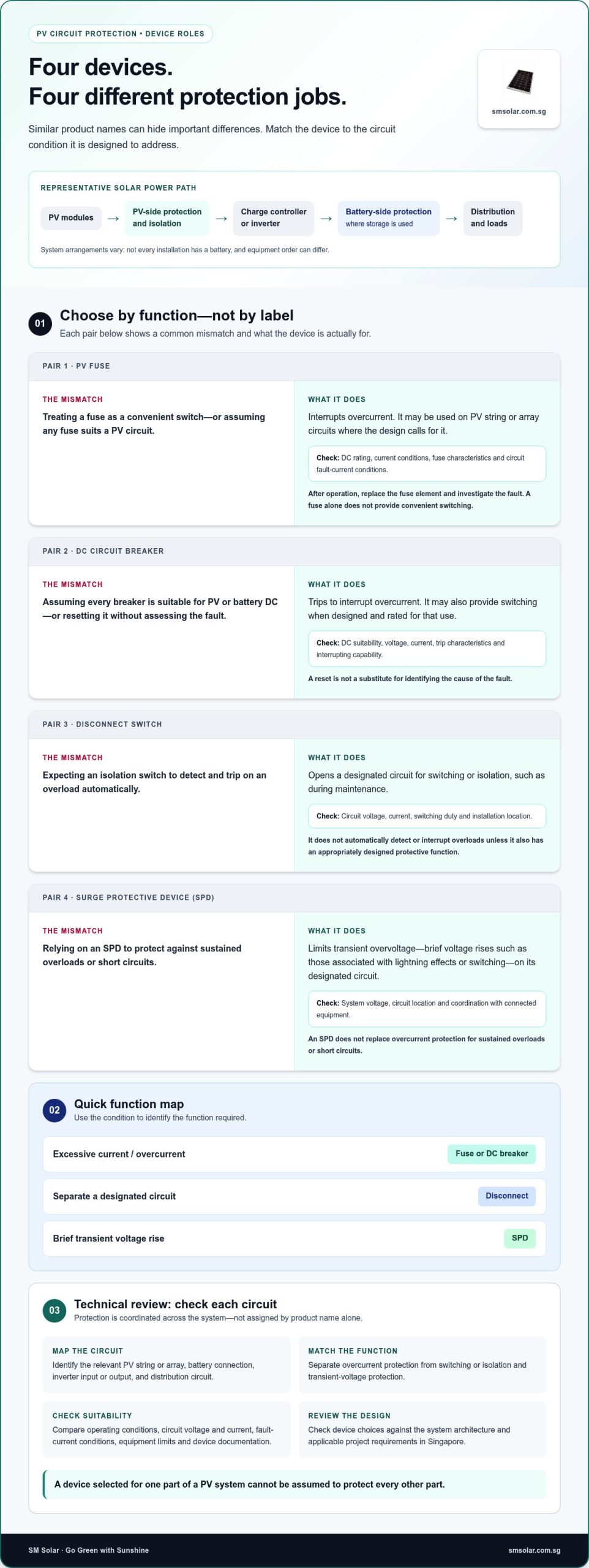
    Circuit protection belongs in the design from the outset. Protection devices are placed on relevant circuits to help manage electrical faults and protect connected conductors and equipment. Their selection and placement depend on the circuit, components and system configuration; they aren’t interchangeable accessories to add after sizing is complete.

    Review the whole path, not just adjacent components. Confirm that the PV array configuration suits the controller, that controller and battery requirements align, and that the inverter suits both the DC source and intended AC loads. Wiring, connection methods and protection-device ratings also require technical review for the project. A mismatch at any interface can constrain the system even when individual components appear suitable.

    For projects such as monitoring installations, this component view helps translate load requirements into a coordinated hardware specification. SM Solar supplies solar system hardware, including panels, charge controllers, batteries, hybrid inverters and circuit protection, supporting designs that account for generation, storage, control and conversion together.

    How to Compare Off-Grid Battery Storage Options

    Compare batteries against the project’s operating requirements, not a headline capacity or chemistry label. For off-grid solar battery storage, the useful comparison is whether a battery can deliver the required energy under the project’s conditions and work with the charge controller and inverter. SM Solar supplies lithium LiFePO4 batteries. Assess other battery categories using current, product-specific manufacturer documentation rather than assumptions about an entire chemistry.

    Use a consistent comparison framework. Record each specification, the conditions under which it applies and any limits that affect the project.

    Comparison factor What to examine
    Usable capacity Nominal capacity, manufacturer-stated usable energy and any stated discharge limits.
    Operating conditions Manufacturer limits for charging and discharging, including the conditions under which published figures apply.
    Lifecycle data Cycle-life or retention claims, with the test conditions and definitions shown alongside them.
    System compatibility Battery voltage and charging requirements against the controller, inverter and system configuration.

    Compare battery chemistry against the application

    LiFePO4 is an option in SM Solar’s battery range, but chemistry alone doesn’t determine suitability. Start with the application: identify the required energy, operating pattern and equipment interface, then compare product documentation against those requirements. If considering other chemistries, use the same criteria and avoid generalising performance from one model to every battery in that category.

    Manufacturer operating conditions are essential context. A cycle-life statement, for example, is meaningful only with its stated test conditions and definition. Compare like with like. If two specifications use different conditions, their figures aren’t directly equivalent. Record the source document and conditions with each entry so the selection remains traceable.

    Nominal capacity, usable capacity and operating limits

    Nominal capacity is the battery’s stated rated capacity. Usable capacity is the energy available for the application within specified operating limits. These are related, but they’re not interchangeable. The manufacturer’s documentation establishes how capacity is defined and the conditions under which it applies.

    Depth of discharge (DoD) describes how much of a battery’s capacity has been discharged. A stated DoD limit affects the amount of energy available for use, so compare usable capacity rather than treating the full nominal rating as available. Don’t infer a universal usable fraction: the applicable limit depends on the product documentation and system configuration.

    For a practical selection, match each candidate’s usable energy and operating limits to the project’s load requirements, then check compatibility with the charging and conversion equipment. Treat lifespan and retention as product-specific claims, not fixed chemistry-wide promises. This keeps the comparison grounded in verifiable specifications and relevant to the actual system.

    Off-Grid Solar Battery Storage: A System Design Guide

    How to Size Off-Grid Solar Battery Storage for a Project

    Specify storage only after the project’s loads and generation have been assessed. Battery selection comes later. This sequence makes the design traceable to actual operating requirements, whether the system serves monitoring equipment, CCTV or water-related loads.

    Storage sizing must follow the load and generation assessment, not precede it.

    1. Inventory the loads. List each device, its electrical demand and operating schedule. Use metered consumption or project records where available. Mark which values are measured and which are estimates, and record the source of each estimate.
    2. Classify load priority. Separate critical equipment from deferrable loads. For a monitoring project, continuous sensing or communications may be critical, while a non-essential load could be scheduled for periods of stronger generation or excluded during constrained operation. The project owner defines these priorities.
    3. Establish the operating requirement. Define when loads must run and the autonomy objective: how long the system should support the selected loads without sufficient solar input. Avoid assuming every load runs continuously or that every project requires the same autonomy period.
    4. Assess generation over the operating period. Use project-specific solar generation information and account for periods when generation may be reduced. Compare the energy expected from the array with load demand over the same period, rather than relying on an average that hides low-generation intervals.
    5. Translate the assessment into storage needs. Estimate the energy required during periods when generation cannot meet demand, then relate that requirement to the battery’s manufacturer-stated usable capacity and operating limits. The result is a design requirement, not a guarantee of supply under every condition.

    Build a project load profile

    Make the load record detailed enough to show timing, not just total consumption. For each device, note operating hours, duty cycle, startup or intermittent use where relevant, and whether its demand is measured or estimated. Identify critical monitoring, CCTV, water-quality or water-monitoring equipment when it applies to the project. This profile provides the basis for prioritisation and makes assumptions visible for later review.

    Translate demand into a storage specification

    Compare the required stored energy with usable battery capacity, not nominal capacity alone. Then cross-check the candidate battery against expected solar generation, charge-controller requirements and inverter input and output needs. Review how the design responds to low-generation periods and document any backup strategy or load-shedding approach. Neither storage capacity nor a backup plan should be treated as a promise of uninterrupted operation.

    For a coordinated specification, align the load assessment with the panels, batteries, charge controllers, hybrid inverters and circuit protection in the design. Explore off-grid system integration with SM Solar when developing the project’s hardware requirements.

    Specify Off-Grid Solar Battery Storage With SM Solar

    Once the load profile, autonomy objective and generation assessment are established, translate them into a coordinated hardware specification. SM Solar supplies off-grid system components wholesale and provides system integration, installation and after-sales maintenance. The battery is one part of that package. Its requirements need to align with the solar array, charge control, power conversion and circuit protection.

    Coordinate the hardware package around the design

    Use the project design as the basis for component selection. Match the battery’s usable capacity and charging requirements to the load profile and expected energy supply. Then align the charge controller with the PV array and battery, and the hybrid inverter with the battery and required loads. Specify circuit protection for the relevant system circuits rather than treating it as an accessory chosen after the other equipment.

    SM Solar supplies lithium LiFePO4 batteries, monocrystalline solar panels, solar charge controllers, hybrid inverters and solar circuit protection. Tie each component to a defined requirement, using manufacturer documentation to assess electrical compatibility. This keeps the specification coherent across the energy path instead of comparing parts in isolation.

    For battery chemistry and protection considerations, consult SM Solar’s lithium battery and solar circuit protection information as part of the component review. The final selection should reflect the project’s electrical design and the specifications of the equipment being integrated.

    Apply the approach to off-grid project requirements

    Off-grid applications differ by load and operating schedule. SM Solar’s documented project examples include water-quality and water-monitoring applications, CCTV and noise monitoring. Each requires its own assessment of which equipment must operate, when it runs and how the system should respond when solar generation is limited. The application informs the design; it doesn’t establish a standard battery size or guarantee a particular operating outcome.

    System integration and installation bring the specified hardware together within the project architecture. SM Solar also provides after-sales maintenance. In each case, the important design link is between project requirements and selected equipment: battery capacity and limits, panel generation, controller charging requirements, inverter output needs and protection-device selection. This component-level coordination is central to specifying off-grid solar battery storage for an actual application.

    To move from design criteria to component selection, review SM Solar’s off-grid solar hardware and prepare the project load profile, generation assumptions and equipment requirements for the specification process.

    Turn the Design Basis Into a Coordinated Specification

    Turn the design basis into a procurement-ready brief. Record approved load priorities, operating schedules, autonomy objectives, generation assumptions, usable-energy requirements and electrical interfaces. Keep measured values distinct from estimates, and note any assumptions that still need resolution. This gives the project team a consistent basis for reviewing component choices and evaluating substitutions against the requirements.

    That discipline applies across off-grid solar battery storage projects, including water-quality, water-monitoring and CCTV applications. SM Solar supplies batteries, charge controllers, solar panels, hybrid inverters and circuit protection devices. Its capabilities also include system integration, installation and after-sales maintenance, linking hardware supply with the broader project workflow without treating a battery as a complete system.

    Use the brief to review the relevant equipment as a coordinated set, with each selection tied to a defined project requirement. Review SM Solar’s off-grid solar hardware range and use your project brief as the basis for a clear, project-specific specification.

    Frequently Asked Questions

    Can an off-grid solar battery system be expanded after installation?

    Yes, if the existing equipment and system design support additional battery capacity. Expansion can be constrained by the inverter, charge controller, battery management system, wiring, protection devices and the manufacturer’s rules for connecting battery units. Before adding storage, review the installed equipment’s specifications and condition, then recalculate the system requirements. A compatible expansion may still require changes to settings or other components.

    How does a battery management system support battery operation?

    A battery management system (BMS) monitors battery operating parameters and manages functions defined by the battery manufacturer. Depending on the design, it may monitor cell voltage and temperature, control charging or discharging, and trigger protective limits. It doesn’t increase the battery’s rated capacity or replace correct system design. The battery documentation should specify how its BMS communicates or coordinates with the inverter and charging equipment, if applicable.

    What happens to an off-grid battery when it reaches its discharge limit?

    At its specified discharge limit, battery controls may restrict or stop further discharge to protect the battery. The effect on connected equipment depends on the system: loads may lose supply, or an inverter may shut down or signal a fault. The system must then recharge the battery before normal operation resumes. For off-grid solar battery storage, understand the configured cut-off and recovery behaviour from the battery and inverter documentation.

    Can an off-grid solar system use a generator as backup?

    Yes, a generator can be included in some off-grid designs, provided the inverter or charging arrangement supports it and the equipment is configured for the generator’s electrical output. The design must account for connection, switching, charging control, protection and safe operation. A generator doesn’t remove the need to size storage around the loads. Its role and operating procedure should be defined in the system plan.

    How should battery storage be maintained in an off-grid system?

    Follow the battery and equipment manufacturers’ maintenance instructions. Keep records of system alarms, operating conditions and any changes in observed performance, and inspect the installation for visible damage, corrosion or loose connections only where safe to do so. Don’t open sealed battery enclosures or alter electrical connections without appropriate technical competence. Maintenance intervals and permissible inspection procedures depend on the specific battery and system configuration.

    Are off-grid solar batteries recyclable at end of life?

    Many battery materials can be recovered through suitable recycling processes, but the correct route depends on the battery chemistry and local collection arrangements. Don’t place a spent battery in general waste or dismantle it. Keep it intact and follow the applicable battery collection or recycling instructions for your location. If a battery is damaged, handle it according to the manufacturer’s safety guidance and the relevant local disposal process.

    Can different battery types be connected in the same system?

    Only when the system and battery manufacturers explicitly allow the proposed combination. Different chemistries, models, ages or capacities can have different voltage characteristics, charging requirements and operating limits. Combining them without an approved design may cause uneven charging or operation outside specified conditions. Check the permitted configuration for the batteries, BMS, charge controller and inverter before making changes. Don’t assume batteries with similar nominal voltage are compatible.
  • Solar Power Distribution: Practical System Guide 2026

    Solar Power Distribution: Practical System Guide 2026

    A solar array can generate power reliably and still fail to serve its loads if the distribution components don’t match. The term solar power distribution equipment covers hardware across different system scales and voltage levels, from DC-side protection and charge control to AC conversion and connection points. What moves power through a solar system, and how do the components fit together?

    The answer depends on the project’s topology, loads and grid connection. Solar system distribution hardware manages power within the installation; utility distribution infrastructure is a separate part of the electricity network. Defining that boundary helps prevent mismatched specifications and incomplete equipment schedules.

    This guide explains the functions and sequence of major components, then maps the DC-to-AC path for common system configurations. You’ll learn how panels, circuit protection, charge controllers, batteries and hybrid inverters fit together, and which interfaces need project-specific review. Use the guide to prepare an equipment schedule for technical review and procurement. SM Solar supplies solar hardware for off-grid and on-grid projects, including panels, batteries, controllers, protection devices and hybrid inverters.

    Key Takeaways

    • Separate solar power distribution equipment within a system from utility-scale transformers and medium- or high-voltage switchgear.
    • Trace the power path from generation through control, protection, optional storage and conversion to loads or the grid.
    • Compare grid-connected and off-grid priorities before building a bill of materials, because their equipment requirements differ.
    • Use project documentation to record topology, loads, storage needs, electrical ratings, connection types and protection requirements.
    • Match project needs to relevant hardware categories, including panels, charge controllers, batteries, circuit protection and roof mounting accessories.

    What Solar Power Distribution Equipment Covers, and What It Does Not

    Solar power distribution equipment is the hardware within a solar installation that routes, converts, controls, stores or protects electrical power between its source and intended loads or connection point. This system-level definition includes components that manage energy along the project’s electrical path. It does not mean every item in the wider electricity network belongs on the solar equipment schedule.

    The scope depends on the project topology, intended loads, storage design and connection requirements. A stand-alone system supplying local loads has different interfaces from a grid-connected system that can export power. Build the equipment list from the documented design rather than starting with a generic package that assumes every installation needs the same components.

    For a broad overview of how panels, inverters and other elements fit into stand-alone and grid-connected installations, see Photovoltaic System Components. The practical distinction is between hardware serving the solar installation and infrastructure serving the wider electricity network.

    Which equipment belongs to a solar power distribution system?

    Group components by their function. Panels generate electrical power. Charge controllers manage charging between a PV source and a battery where that arrangement is used. Batteries store energy, inverters convert DC power to AC where required, and circuit protection devices help protect electrical circuits. A system may include some or all of these categories, depending on its architecture and loads.

    • Generation: Solar panels supply power to the system.
    • Control and storage: Charge controllers and batteries serve designs that include battery charging and storage.
    • Conversion and protection: Inverters provide DC-to-AC conversion where needed, while circuit protection is selected for the documented circuits.

    This is a functional map, not a standard bill of materials. A project without battery storage won’t use the same component combination as one designed to store energy. In the equipment schedule, identify each component’s role and the interfaces it must support in the specific design.

    How DC-side hardware differs from utility distribution equipment

    DC-side solar hardware operates within the installation’s source, storage and load arrangement. Transformers and substations, by contrast, belong to the broader electrical network and may serve transmission or distribution functions beyond the solar array. Medium- or high-voltage switchgear, such as the medium-voltage equipment produced by manufacturers like Africa Switchgear & Transformers, is also network-level equipment, not another name for a solar circuit protection device.

    The difference is one of role and scale. A circuit protection device is selected for a particular circuit in a solar system; a transformer changes voltage between parts of an electrical network. They serve different interfaces and aren’t interchangeable procurement categories. Depending on the project, utility infrastructure may connect to a solar installation at its grid interface. That does not make network equipment equivalent to the installation’s DC-side hardware.

    To define the project scope, first set the solar system boundary: where generation enters, which equipment manages or converts power, whether storage is included, and where power is delivered. Then distinguish those components from any network-side equipment identified in the connection design. This keeps terminology precise and helps the equipment schedule reflect the actual topology, intended loads and connection requirements.

    How Solar Distribution Equipment Moves Power Through a System

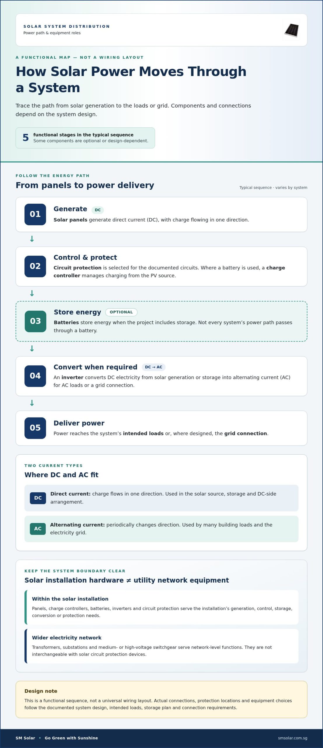
    Follow the energy path to see how the components relate. Solar panels generate direct current (DC), in which charge flows in one direction. Alternating current (AC), used by many building loads and the electricity grid, periodically changes direction. Where included, a charge controller manages charging from the PV source to a battery. An inverter converts DC to AC when the design requires AC loads or a grid connection.

    A typical functional sequence is generation, DC-side control and protection, optional storage, conversion where required, then delivery to loads or the grid. This describes the roles of solar power distribution equipment, not a universal wiring layout. Actual connections and protection locations follow the system design and verified project documentation.

    From solar panels through charge control and storage

    A charge controller regulates the relationship between the solar panels and a connected battery, managing charging within the designed system. A battery is included when the project calls for energy storage. Its position and connection depend on the system architecture, so not every panel-to-load path passes through storage.

    Typical DC-side relationship where a battery is included:

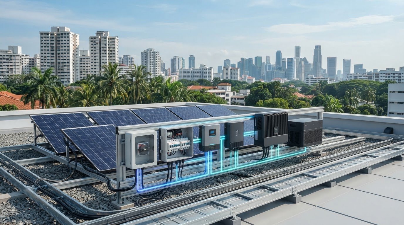
    Solar panels → DC-side protection and control → charge controller → battery → inverter or DC loads

    This is a functional illustration, not installation instructions. Some systems use a different component arrangement or omit components that aren’t needed for their intended operation.

    Where inverters and protection devices fit

    An inverter converts DC electricity from solar generation or storage into AC electricity for AC loads. In a grid-connected design, the conversion equipment also forms part of the system’s interface with the grid. In an off-grid design, power is delivered to local loads, with storage included if the project requires it. The DOE Solar Energy Technologies Office discusses solar technology and grid integration, providing wider context on how a system can connect to the electricity network.

    Protection devices may be needed at relevant circuit and equipment boundaries on the DC side, AC side or both. Their selection and placement depend on the project topology and documented electrical requirements. Don’t treat a simple diagram as a protection schedule or assume one layout applies to every system. For component-level detail, consult the existing solar circuit protection guide.

    When preparing an equipment schedule, mark where generation enters, where control or storage occurs, where DC-to-AC conversion is needed, and whether power serves local loads, the grid or both. This makes interfaces clearer for technical review. Project teams sourcing panels, charge controllers, batteries, inverters and protection can also review SM Solar’s solar hardware range against their system design.

    Grid-Connected and Off-Grid Equipment: Compare the Design Priorities

    System topology determines where generated power can go and which equipment must manage that flow. A grid-connected system is designed to operate with an electricity network interface. An off-grid system serves loads without relying on that interface. Both use solar equipment, but their operating objectives differ. Treating them as interchangeable can leave a project schedule with components that don’t match the intended loads or operating conditions.

    The comparison below shows typical design considerations, not mandatory equipment lists. Storage, conversion and control requirements depend on the project architecture. For grid-connected projects, base grid-interface requirements on the project documentation and applicable requirements rather than assumptions taken from another jurisdiction.

    Design consideration Grid-connected system Off-grid system
    Power destination Local loads and, where the design permits, the grid connection Loads served within the standalone system
    Storage role Included when the project design calls for storage Often considered to support operation when solar generation and load don’t coincide
    Conversion Inverter interfaces solar DC power with AC loads and the grid connection as designed Conversion is selected to suit the required loads and system arrangement
    Control considerations Coordinate system operation with the defined grid interface and project requirements Plan charge control, storage use and supply against the intended load profile

    Distribution priorities in grid-connected systems

    In a grid-connected design, conversion equipment and the system interface support the movement of solar power to AC loads and the connection point. Storage may be included, but it isn’t an automatic requirement. Keep these general equipment functions separate from local interconnection rules, which depend on the project and market. Use project-specific documentation rather than applying standards or compliance assumptions from another jurisdiction as general guidance.

    For the equipment schedule, identify the grid interface, intended loads and any storage provision. Then align component roles with those documented requirements. A component’s presence in another grid-connected design doesn’t establish that it belongs in this one.

    Distribution priorities in off-grid systems

    Off-grid planning centres on supplying defined loads without a grid connection. Charge control and battery storage feature in many such designs, but requirements depend on how and when loads operate and on the intended operating conditions. Record the load profile and storage objective before settling on the equipment combination. SM Solar supplies hardware for off-grid projects; these applications provide context, not proof of a particular system’s performance.

    Select solar power distribution equipment against the project topology and load requirements, not a generic grid-versus-off-grid checklist. Review where power is needed, how the system will serve that demand, and which equipment functions the design actually requires. This gives technical reviewers a clearer basis for assessing component selection and interfaces.

    Solar Power Distribution: Practical System Guide 2026

    How to Specify Solar Power Distribution Equipment for a Project

    Build the equipment schedule from the project design, not from a standard product bundle. Before selecting solar power distribution equipment, establish the system topology, energy source, intended loads, storage requirements and operating conditions. Then use verified project documents to record electrical ratings, connection types and protection requirements. This ties component selection to actual interfaces and helps technical reviewers identify missing information.

    Minimum selection inputs: topology, source, loads, storage objectives, operating conditions, documented electrical ratings, connection types and protection requirements.

    Create an equipment schedule around system interfaces

    Give each item a defined function and identify what it connects to. Record the source document for its requirements, such as the project design or equipment documentation. Make dependencies visible too: a controller must suit the designed panel-to-battery relationship, while battery and inverter interfaces must align with the intended storage and load arrangement.

    Schedule field What to record
    Component and function Panel, charge controller, battery, inverter, or circuit protection device, with its role in the system
    Electrical interface Documented ratings and connection types for the relevant source, storage, load, or grid interface
    Dependencies Related components and design conditions that affect selection
    Project reference Drawing, specification, or other verified document supporting the recorded requirement

    Don’t fill gaps with assumed ratings or sizing rules. Flag missing values for technical review against the project documentation instead. This makes the schedule useful for procurement without treating a typical configuration as a universal specification.

    Review protection, mounting and procurement details

    Include circuit protection and relevant mounting accessories in the equipment schedule, even though they serve different functions. Protection items relate to electrical circuits and interfaces; pole mounts, roof clamps and brackets support panel mounting. Record the project basis for each selection. For device-specific considerations, refer to the solar circuit protection guide. For panel technology decisions, consult the monocrystalline solar panels technical overview.

    Before procurement, compare the schedule with the system drawings and confirm that every listed component has a documented purpose, interface and requirement. Review dependencies across panels, controllers, batteries and inverters as a set. This helps expose mismatches before purchasing and provides a traceable basis for technical review.

    For project teams assembling a schedule around solar hardware, review SM Solar’s solar equipment supply.

    SM Solar’s Role in Supplying Solar Power Distribution Equipment

    SM Solar is a wholesale distributor of solar hardware, with a core focus on 12 V DC solar products. For project teams building an equipment schedule, its portfolio covers key system functions: generation, charge control, storage, circuit protection, conversion and panel mounting. The right combination depends on the project design. It isn’t a fixed package that assumes every installation needs every component.

    SM Solar was established in 2008 and became a private limited company in 2016. The company supplies hardware for off-grid and on-grid projects, giving project teams access to components for different system arrangements. Its company profile also lists clients for off-grid and on-grid projects. These examples provide project context, not a performance claim about any particular system.

    A wholesale portfolio for solar project equipment

    SM Solar’s product categories can be mapped to equipment schedule requirements:

    • Generation: Monocrystalline solar panels.
    • Charge control and storage: Solar charge controllers and batteries, including Lithium LiFePO4 batteries.
    • Conversion: Hybrid inverters.
    • Electrical protection: Solar circuit protection.
    • Panel mounting: Solar panel pole mounts, standing seamlock roof clamps and roof mounting brackets.

    These categories support different parts of a system, but the schedule should reflect the project’s topology, intended loads and documented interfaces. A design with storage has different component dependencies from one without it; mounting accessories also depend on the selected installation arrangement. As a wholesale hardware source, SM Solar supplies project teams assembling component schedules around defined requirements, rather than a one-size-fits-all bundle.

    From equipment supply to project implementation

    For end users, SM Solar also provides system integration, installation and after-sales maintenance. These capabilities extend beyond component supply to project implementation and ongoing support. The company’s listed off-grid and on-grid client projects show experience in both application contexts, without implying that one system configuration or equipment set suits every project.

    For procurement planning, project teams can align the equipment schedule with the chosen system design, identify required categories and document interfaces for technical review. This creates a clearer basis for coordinating supply and integration requirements, whether the project is off-grid or grid-connected. SM Solar’s solar hardware portfolio includes panels, controllers, batteries, circuit protection, mounting accessories and hybrid inverters.

    Discuss solar power distribution equipment for your project and its equipment supply and integration requirements with SM Solar.

    Move Your Solar Project from Design to Procurement

    Turn the project’s design intent into a coordinated procurement brief. Bring the system drawings, load requirements, storage objectives and documented equipment interfaces into one review. Resolve open technical decisions before preparing purchase orders, so each item has a defined role and a traceable project requirement.

    A focused review also helps engineering and procurement teams work from the same component schedule. Together, they can identify dependencies and flag information that still needs technical resolution. This gives solar power distribution equipment selection a practical basis without relying on assumptions or generic packages.

    For project teams planning equipment supply alongside implementation, SM Solar can support discussions about project requirements and integration needs. Discuss your solar project equipment requirements and take the next step toward a coordinated schedule.

    With a clear brief and defined interfaces, your team can move forward with greater confidence.

    Frequently Asked Questions

    Is solar power distribution equipment the same as a distribution board?

    No. Solar power distribution equipment refers to the wider set of components that manage electrical power in a solar installation; a distribution board is one possible board or assembly within a system. Terminology can vary between project documentation and electrical designs. A schedule may, for example, identify a specific board separately from an inverter or protection device. Use the project drawings and equipment schedule to identify the intended component rather than treating the terms as interchangeable.

    Can an off-grid solar system operate without a battery?

    Yes, some off-grid designs may supply loads while solar generation is available without storing energy in a battery. Whether that arrangement suits a project depends on when power is generated and when loads need it. If loads must be served when generation is unavailable, the design may require storage or another defined supply strategy. Compare the load profile with the intended operating conditions before deciding whether a battery belongs in the system.

    What happens if an inverter cannot support the connected AC loads?

    The system may not operate the connected equipment as intended, but the specific result depends on the inverter and load characteristics. Check the inverter’s documented ratings against the loads and their operating requirements using project documentation. For example, the schedule should account for every AC load the design expects the inverter to serve, not just the equipment’s general category. Resolve any mismatch during design review rather than assuming a particular fault will occur.

    Does every solar system need a combiner box?

    No. A combiner box is not a universal requirement; whether it belongs in a design depends on the PV configuration, string arrangement and electrical design. A project with a different array layout may use a different arrangement. Don’t add one solely because it appears in another system’s equipment list. Refer to the system drawings and applicable project requirements to determine the intended configuration, without treating this answer as a wiring prescription.

    Can solar distribution components from different manufacturers work together?

    Potentially, but manufacturer names alone don’t establish compatibility. The relevant electrical ratings, connection interfaces, operating requirements and overall system design must align. For example, review the documented relationship between a charge controller and battery, as well as the interfaces between the inverter and connected equipment. Assess the equipment documentation and system schedule together. Without supporting technical information, don’t assume a particular combination is approved or suitable.

    What information should a project team provide when sourcing solar distribution equipment?

    Provide the system topology, intended loads, storage requirements, component interfaces and operating conditions, along with relevant drawings and specifications. These inputs help define a coherent equipment schedule and support technical review. For instance, clarify whether the system is grid-connected or off-grid and identify the equipment the design is intended to serve. SM Solar supplies solar hardware and provides system integration capabilities for projects requiring equipment coordination.

  • Solar Power Hardware Procurement: An EPC Project Guide

    Solar Power Hardware Procurement: An EPC Project Guide

    A solar hardware package is more than a list of individually capable products. It is a coordinated set of components that must meet the project’s electrical, mechanical and delivery requirements. Solar power hardware procurement can lose alignment when specifications are assessed in isolation, leaving EPC teams to resolve compatibility or scope gaps during integration.

    Panels, charge controllers, batteries, inverters, circuit protection and mounting hardware each have defined roles. The interfaces between them determine whether the package fits the system design. Supplier comparisons are more useful when they assess project fit, not just product features.

    This guide sets out a project-led framework for defining procurement scope against system requirements, comparing hardware and supply options using consistent criteria, and coordinating sourcing with integration and delivery planning. It covers the component categories to consider, the compatibility details that affect package selection, and how a hardware supply partner such as SM Solar can support planning across its DC-focused product range. The aim is to build the procurement process around project requirements from the start.

    Key Takeaways

    • Start solar power hardware procurement with the project’s system architecture, operating context and delivery requirements.
    • Map panels, charge controllers, batteries, hybrid inverters and circuit protection to the approved system design.
    • Compare supply options against consistent criteria, separating mandatory specifications from preferred supplier capabilities.
    • Use a controlled workflow from scope definition and offer evaluation through ordering, delivery coordination and receipt inspection.
    • Plan component packages around the project scope, including roof clamp accessories and other DC-related hardware.

    Solar power hardware procurement: define the project before sourcing

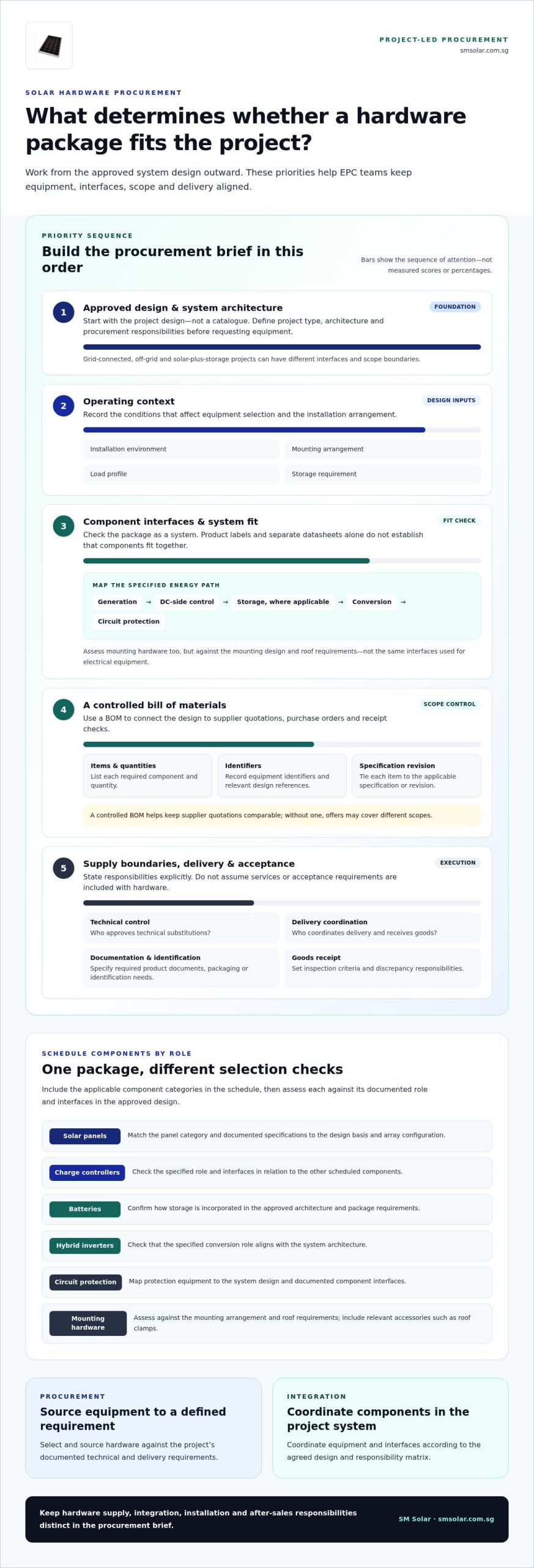
    Solar power hardware procurement means sourcing components against a project’s documented technical and delivery requirements. For an EPC team, the starting point is the approved design, not a catalogue. Define the project type, system architecture, operating context and procurement responsibilities before requesting equipment. A grid-connected array, an off-grid system and a solar-plus-storage configuration can have different component interfaces and scope boundaries.

    Record the operating conditions that affect equipment selection, including the installation environment, mounting arrangement, load profile and any storage requirement. The Solar power overview provides broader context on how solar technologies convert energy into electricity. Procurement decisions, however, should follow the project’s selected design and engineering documentation.

    Separate hardware supply from integration, installation and after-sales responsibilities in the procurement brief. State who approves technical substitutions, coordinates delivery, receives goods and resolves discrepancies. A bill of materials (BOM) connects the design to commercial documents: it identifies each required item and quantity, supports comparable supplier quotations, and provides a reference for purchase orders and receipt checks. Without a controlled BOM, quotations may cover different scopes even when they appear to describe similar packages.

    Hardware procurement sources components to meet a defined system requirement; system integration coordinates those components within the project system.

    What belongs in an EPC solar hardware procurement scope?

    Build the scope from approved design documents. Identify each component category, quantity and project-specific specification, including applicable panels, charge controllers, batteries, hybrid inverters, circuit protection and mounting hardware. Do not rely on product labels alone. Record design references and required interfaces so each quotation can be assessed against the same requirements.

    • Component schedule: List equipment, quantities, identifiers and the relevant design specification or revision.
    • System interfaces: Document how modules connect with storage, conversion, control and protection equipment, including dependencies that affect component selection.
    • Supply and acceptance: State the required product documentation, delivery coordination details, packaging or identification needs, and goods-receipt inspection criteria.

    Keep these requirements distinct in the brief. Documentation, delivery and acceptance are procurement requirements, not implied equipment features. For development projects requiring highway access strategies and planning application documentation, consultancies such as ML Traffic Engineers UK can handle the necessary transport planning requirements. This helps the EPC team identify responsibilities before quotation and order placement.

    How procurement differs from system integration

    Procurement covers selecting and sourcing equipment that meets a defined requirement. Integration covers coordinating equipment and interfaces within the project system, according to the agreed design and responsibility matrix. Installation and after-sales support are separate scope considerations. Assign them explicitly rather than assuming they are part of a hardware order.

    SM Solar is a wholesale distributor of solar hardware, including panels, charge controllers, batteries, circuit protection devices, roof clamp accessories and other DC-related products, with a core focus on 12 V DC products. The company also provides system integration, installation and after-sales maintenance for end users. These capabilities can inform project planning, while each EPC procurement brief should define its equipment and service boundaries.

    Map solar hardware components to their role in the project

    A component schedule is useful only when each item is tied to its function and interface in the approved system design. For solar power hardware procurement, the key question is not whether a panel, battery or inverter looks suitable in isolation. It is whether the selected equipment matches the architecture and connects correctly with the other specified components. The Solar & Storage Supply Chain resource outlines upstream solar manufacturing stages. EPC schedules translate project design into equipment requirements.

    Start with the energy path shown in the design: generation, DC-side control, storage where applicable, conversion, and circuit protection. Then distinguish electrical equipment from mounting hardware. Both belong in the schedule, but their selection criteria differ. A roof clamp, for example, is governed by the mounting design and roof requirements, not the same interfaces used to assess a charge controller.

    Coordinate panels, charge controllers, batteries and inverters

    Use the approved specifications to map how modules connect to control equipment, how storage is incorporated, and how the inverter serves the system architecture. Review technical documentation as a package. Check that stated interfaces and intended functions align across the relevant components, rather than treating separate product datasheets as proof of system fit. The monocrystalline solar panels technical overview and lithium LiFePO4 battery supplier guide provide category-specific context for those schedule entries.

    • Solar panels: Match the panel category and documented specifications to the design basis and array configuration.
    • Charge controllers: Check their specified role and interfaces against the DC-side design and connected equipment.
    • Batteries: Include the specified battery type and system interfaces where storage forms part of the design.
    • Hybrid inverters: Confirm their role in the defined conversion and system architecture.

    This map helps expose missing dependencies before quotation. SM Solar’s DC-focused portfolio includes panels, charge controllers and batteries, which can be considered as related categories within a project-defined package.

    Include mounting and circuit protection in the equipment schedule

    Mounting and protection are not incidental accessories. Include the mounting arrangement in the design basis, then schedule the roof clamps, brackets or pole mounts specified for it. Standing seamlock roof clamps and roof mounting brackets should be assessed against the project’s roof and mounting requirements, not assumed to be interchangeable. List circuit protection devices against their designated positions and functions in the system documentation. The solar circuit protection devices guide offers further category detail.

    Keep these items visible in the bill of materials so they carry through quotation, ordering and receipt checks. EPC teams planning a DC component package can review SM Solar’s solar hardware range against the project design.

    Compare solar hardware procurement options with consistent criteria

    Compare every quotation against the same project baseline. In solar power hardware procurement, a price comparison is not useful if offers differ in equipment scope, specification alignment or assigned responsibilities. Separate mandatory project requirements from preferred supplier capabilities before evaluating options. Mandatory items come from approved design and procurement documents; preferences can distinguish offers without changing the technical basis.

    Criterion
    What to compare
    Specification alignment
    Match equipment descriptions and stated specifications to the approved project documents. Record deviations for technical review.
    Documentation
    Compare the documents provided with the project’s defined submittal and acceptance requirements.
    Component scope
    Check categories and quantities against the bill of materials. Identify exclusions, alternatives and items left for others to supply.
    Project coordination
    Record stated responsibilities for order coordination, delivery information and any separately scoped project support.

    Use a common response format for all offers. Require each quotation to identify equipment, quantities, exclusions and responsibilities clearly. If an item is marked “by others,” record who is responsible for supplying it; otherwise, the package may have a scope gap. Do not infer price suitability, certification status, lead time, warranty terms or supplier performance from incomplete information. Assess only what the quotation and supporting documents state against the project criteria.

    Evaluate technical fit and documentation

    Review equipment descriptions against the approved design, not broad category names. Note interface assumptions, proposed substitutions and unresolved technical dependencies in a comparison record. Apply the same documentation and acceptance requirements to each option. This creates a traceable basis for technical approval and helps prevent a preferred capability from being mistaken for a mandatory specification.

    Assess supply scope and project support

    Map each quoted package to the bill of materials, marking included, excluded and substituted items. Assess integration, installation and after-sales maintenance as distinct support capabilities. Tie responsibility to the project scope rather than assuming it is included with a hardware quotation. The solar energy equipment supplier buyer’s guide provides broader evaluation context.

    Once the comparison criteria are set, record the technical decision and any outstanding conditions before purchase approval. EPC teams assessing component categories can review SM Solar’s solar hardware range against project-defined requirements.

    Solar Power Hardware Procurement: An EPC Project Guide

    Use a controlled procurement workflow from specification to receipt

    A defined workflow keeps the approved design connected to supplier responses, purchase orders and goods receipt. In solar power hardware procurement, assign an owner to each handoff. A responsibility matrix can identify who approves specifications, controls purchasing, coordinates delivery and inspects received equipment. Roles may vary by EPC, but assign each responsibility before issuing the request.

    1. Define scope. Engineering compiles the equipment schedule from approved project documents, records the applicable revision and identifies required documentation, delivery and acceptance conditions.
    2. Issue requirements. Procurement distributes the same schedule and response format to suppliers. Request clear equipment descriptions, quantities, stated exclusions, documentation and responsibility boundaries.
    3. Evaluate offers. Engineering reviews technical alignment and resolves interface questions. Procurement compares scope and commercial terms against the same project baseline, recording deviations and open queries.
    4. Place orders. Purchasing issues orders only after required approvals and clarifications are recorded. The order should reflect the accepted offer, approved substitutions and applicable schedule revision.
    5. Inspect receipts. The assigned receiving or quality role compares delivered items and accompanying documents with the purchase order and approved equipment schedule. Record discrepancies and route them through the project’s established process.

    Prepare the request and evaluate supplier responses

    Issue one controlled equipment schedule with project requirements and requested documentation so responses can be compared consistently. Review technical fit, package scope, exclusions and coordination responsibilities separately. If an offer differs from the schedule, record the discrepancy and obtain an approved clarification before making a purchase commitment. Keep unresolved technical dependencies visible rather than treating silence as acceptance.

    Control changes, delivery and equipment receipt

    Maintain a record of specification revisions, substitutions, exclusions and decisions, then carry approved changes into purchasing and handover records. Coordinate delivery against the current order and schedule. For broader commercial site works where freight staging and heavy vehicle logistics impact surrounding road networks, transport consultancies like mltraffic.com.au provide traffic engineering and access planning. At receipt, check item descriptions, quantities and available documentation against those records. If a discrepancy appears, document it and escalate it through the project’s assigned procurement and quality process before closing receipt.

    Use consistent records across engineering, procurement and receiving. A traceable change history makes it easier to identify which requirement was approved, which equipment was ordered and what arrived. Traceable procurement records keep decisions and responsibilities visible at each project handoff, helping teams manage coordination gaps.

    For project-led sourcing, review SM Solar’s solar hardware range alongside the approved equipment schedule and procurement requirements.

    Work with SM Solar on project-led solar hardware sourcing

    Project-led solar power hardware procurement starts with the approved bill of materials, then connects each required item to a documented technical requirement. SM Solar is a wholesale distributor of solar hardware, including solar panels, charge controllers, batteries and circuit protection devices. Its portfolio also includes roof clamp accessories and other DC-related products, with a core focus on 12 V DC products. This range can inform a project-defined sourcing scope without implying that every project needs the same component package.

    SM Solar was established in 2008 and became a private limited company in 2016. Its wholesale distribution role is distinct from its system integration, installation and after-sales maintenance capabilities for end users. An EPC brief should identify which capabilities apply to the project and assign each responsibility separately.

    Match SM Solar’s hardware categories to the project scope

    Use the approved bill of materials as the starting point. Match each listed component to its project specification, quantity and system interface. For example, a schedule may include panels, charge controllers, batteries and circuit protection alongside roof clamps or brackets where the design specifies them. The schedule, rather than an assumed standard package, determines which categories are relevant.

    • Panels and control equipment: Identify the specified panel and charge controller categories, then tie each to the relevant design documentation.
    • Storage and protection: List batteries and circuit protection devices only as required by the project scope, with relevant interface requirements recorded.
    • Mounting and DC-related items: Include roof clamp accessories and other DC-related products where they appear in the approved design and equipment schedule.

    This category-by-category approach keeps product selection anchored to the project’s technical requirements. It also gives procurement and engineering teams a shared reference for discussing inclusions, substitutions and scope boundaries.

    Prepare a clear procurement brief

    A concise, complete brief helps structure a focused discussion of hardware sourcing and any separately defined integration scope. Include the project overview, approved equipment schedule and applicable technical documents. Identify quantities, required documentation, delivery coordination needs and the project’s acceptance process. If integration or other support is required, describe its intended scope and interfaces separately from the equipment list.

    • Attach the current bill of materials and relevant design revisions.
    • List equipment categories, quantities and project-specific technical requirements.
    • State delivery coordination, documentation and receipt requirements.
    • Define any project-specific integration or end-user support responsibilities.

    With these details prepared, EPC teams can discuss sourcing against an actual project scope rather than a generic product list. Explore SM Solar’s solar hardware supply for project-led procurement planning.

    Carry a clearer procurement basis into your next project

    Make the procurement brief a controlled project reference, not a one-time request document. After each package, capture approved substitutions, recurring clarification points and receipt discrepancies in the team’s procurement records. Use those lessons to refine future equipment schedules and review gates, while keeping each project’s requirements tied to its own approved design. This gives engineering and purchasing teams a shared basis for decisions before orders are released.

    For the next solar power hardware procurement, begin with the project documents and identify which component categories belong in scope. Then align technical review, purchasing and goods receipt around that same baseline. A focused sourcing discussion is easier to start when the equipment schedule and responsibility boundaries are ready.

    Explore SM Solar’s solar hardware supply as you develop a project-specific sourcing scope. A defined procurement basis gives your team a clearer reference for the next project.

    Frequently Asked Questions

    What does solar power hardware procurement include?

    Solar power hardware procurement covers sourcing specified equipment and defining what the supply scope excludes. The brief can distinguish hardware supply from engineering approval, site installation and commissioning responsibilities, which may sit with different project parties. For example, if equipment is supplied without installation, state who manages on-site handling and installation coordination. This boundary clarifies the purchase scope and helps avoid treating a component order as a complete project delivery package.

    How do EPC teams compare solar hardware suppliers?

    EPC teams can compare suppliers using a shared response template tied to the project’s requirements. Check whether each offer identifies the relevant equipment, quantity, supporting documents, exceptions and assigned responsibilities. Record each deviation beside the corresponding schedule line, rather than leaving it in general quotation notes. This helps engineering review technical differences while procurement compares scope, without treating an unstated detail as an agreed commitment.

    Which components should a solar hardware procurement package cover?

    The package should cover components required by the approved design, not every category available in the market. Depending on the system, the schedule may include panels, charge controllers, batteries, hybrid inverters, circuit protection devices and mounting hardware such as clamps or brackets. Use the bill of materials to show which items are in scope and identify associated items supplied under separate packages. That distinction supports clearer purchasing and receipt checks.

    Why should solar components be assessed as a system?

    Solar components should be assessed as a system because individual equipment descriptions do not establish that selected items fit together within the project architecture. A component may meet its own stated requirement but still leave an interface, control or protection dependency unresolved. Reviewing related equipment together helps engineering identify those dependencies before ordering and gives procurement a clearer basis for evaluating substitutions. The approved design remains the reference for determining fit.

    What documents should an EPC include in a solar hardware procurement brief?

    An EPC brief should include the current equipment schedule, relevant design drawings or diagrams, applicable technical specifications and required submittal documents. Add the project’s delivery instructions, goods receipt process and acceptance criteria so the supply scope can be administered consistently. Identify document revisions and the person or function responsible for technical approval. This gives suppliers a defined reference and helps the EPC trace decisions from enquiry through order and receipt.

    How can procurement teams manage substitutions or specification changes?

    Manage substitutions through documented review and approval before updating purchase records. Identify the affected schedule item, the proposed change and any interface documents that engineering needs to reassess. Record the decision and its revision reference, then align the quotation, purchase order and receiving records with the approved change. If equipment arrives against an earlier revision, the receiving team can identify the discrepancy and route it through the project’s change-control process.

    Does SM Solar provide solar hardware as well as project support?

    Yes. SM Solar is a wholesale distributor of solar hardware, including solar panels, charge controllers, batteries, circuit protection devices, roof clamp accessories and other DC-related products. It also provides system integration, installation and after-sales maintenance for end users. These are distinct capabilities, so EPC teams should define hardware supply and any project support separately in the scope and tie requirements to the approved design.

  • Solar Energy Equipment Supplier: A Buyer’s Guide for 2026

    Solar Energy Equipment Supplier: A Buyer’s Guide for 2026

    A supplier with the broadest catalogue may still be the wrong fit for your project. Choosing a solar energy equipment supplier means checking how components work together, whether the supplier’s distribution model suits your procurement needs, and what support is available beyond product supply.

    Procurement can become fragmented when panels, batteries, controllers, inverters and protection devices come from separate sources. In a 12 V DC system, differences in specifications and interfaces can create coordination issues across the equipment package. Start with the system design, then compare suppliers against the same equipment schedule and support requirements.

    This guide sets out a practical framework for evaluating solar equipment suppliers in Singapore. It explains how key component categories fit into a system, what to consider for wholesale and system integration, and how to distinguish product supply from broader project support. SM Solar is a Singapore-based wholesale distributor focused on 12 V DC solar products. The company also provides system integration, installation and after-sales maintenance for end users. Use the steps below to assess supplier fit against your project’s equipment and support requirements.

    Key Takeaways

    • Separate equipment supply from integration, installation and utility services so procurement responsibilities are clear.
    • Map panels, charge controllers, batteries and circuit protection as a system, then compare specifications against the design.
    • Compare each solar energy equipment supplier by product scope, wholesale model, documentation and project support.
    • Use a project brief, bill of materials, technical review and delivery coordination to structure procurement.
    • SM Solar supplies equipment for 12 V DC project requirements, including panels, batteries, charge controllers, circuit protection devices and roof clamp accessories.

    What a Solar Energy Equipment Supplier Provides to Project Buyers

    Definition: A solar energy equipment supplier sources and distributes hardware specified for a solar project. Equipment supply is distinct from designing and delivering a complete system, carrying out installation, or providing electricity as a utility. Define these responsibilities at the start of procurement so the project team knows who is accountable for each part of the work.

    For installers, system integrators, engineering, procurement and construction (EPC) firms, and other project buyers, wholesale distribution can provide a route to equipment across relevant categories. A broad product range is only one consideration. Assess whether the products suit the design, whether their documentation supports technical review, and whether the supplier’s support matches the project scope.

    Supplier, manufacturer and system integrator: distinct procurement roles

    A utility has a different role: it supplies electricity through the applicable energy network, rather than project hardware. Understanding these boundaries clarifies responsibility for product selection, system design, delivery and installation. Record each responsibility in the procurement plan, including any support required after installation.

    Wholesale solar equipment categories in a project

    A project package may include solar panels, charge controllers, batteries and circuit protection devices, alongside mounting hardware. Each category has a distinct place in the equipment schedule. The components of a solar panel system provide useful context for understanding how generation equipment fits within a broader system.

    • Generation: Solar panels provide the system’s solar input.
    • Control and storage: Charge controllers and batteries are selected according to the system design and intended operating requirements.
    • Protection: Circuit protection devices form part of the electrical equipment package.
    • Mounting: Roof clamp accessories, roof mounting brackets and solar panel pole mounts support the planned mounting arrangement.

    These are category-level roles, not a compatibility specification. Check voltage, current, configuration and other requirements against the project design and the relevant product documentation. A product category alone does not establish that two components are suitable for use together.

    SM Solar is a Singapore-based wholesale distributor focused on 12 V DC solar products. Its equipment categories include solar panels, charge controllers, batteries, circuit protection devices and roof clamp accessories. The company also provides system integration, installation and after-sales maintenance for end users. Buyers can plan equipment supply and additional project support together, while defining the scope of each function.

    Use the supplier role as a starting point for procurement. List the required equipment, identify the project functions that need support, and compare the product range and documentation with the design. Next, examine how the equipment categories interact within the system.

    How Solar Equipment Categories Work Together in a System

    Solar components function as a connected electrical system, not as independent catalogue items. Panels provide electrical output. In systems designed to use them, charge controllers manage the connection between the panel array and battery storage. Batteries store energy for later use, while circuit protection devices form part of the system’s electrical protection architecture. The project design determines the actual configuration.

    A DC-focused system should not automatically be treated as a grid-tied system. Grid interaction, storage and conversion requirements vary by design. Hybrid inverters may be relevant to some configurations, but their role and compatibility depend on the intended system architecture. A U.S. Department of Energy overview of solar technologies provides broader context; project decisions still require the applicable equipment documentation and design review.

    Solar panels, charge controllers and battery storage

    Panel selection establishes part of the system’s electrical input. The controller must suit the panel arrangement and battery configuration, while the battery must align with the system’s intended voltage and operating requirements. Before comparing products, identify the system voltage, design intent and relevant component specifications. For panel-level context, SM Solar’s monocrystalline solar panels technical overview explains the category without replacing project-specific review.

    Component Functional role Procurement check
    Solar panels Provide the system’s solar electrical input. Review output characteristics against the planned configuration.
    Charge controllers Manage the connection between panels and battery storage where used. Match controller specifications to the panel and battery design.
    Batteries Store energy for system use as designed. Check battery specifications against system voltage and operating requirements.
    Circuit protection Forms part of the electrical protection architecture. Confirm device selection and placement against the design.
    Mounting accessories Connect panels to the intended installation structure. Match the mounting method to the structure and installation plan.

    Circuit protection and mounting accessories

    Consider protection devices as part of the complete PV equipment architecture. The design and component documentation should inform their selection and placement. For category-level detail, the solar circuit protection devices guide covers their role. Roof clamps, brackets and pole mounts serve a different interface: they secure equipment to the planned mounting structure. Their suitability depends on the installation arrangement, not electrical compatibility alone.

    Before finalising a bill of materials, review the component specifications alongside the system design. A solar energy equipment supplier can supply the relevant categories for review, and system integration can help coordinate components when required. Buyers planning a 12 V DC package can review SM Solar’s solar equipment supply against their project requirements.

    How to Compare Solar Energy Equipment Suppliers for Project Fit

    Start a supplier comparison with the project bill of materials, not the size of a catalogue. A solar energy equipment supplier may carry relevant hardware but still be a poor fit if the product scope, documentation or support model does not match the procurement requirement. Use product range as an initial screen, then assess the proposed items against the system design and verified specifications.

    Evaluate product scope and technical coordination

    Map each required item to a product category, then review the relevant datasheets for electrical characteristics and interface requirements. For a DC-focused project, assess the proposed panels, charge controllers, batteries and circuit protection as a connected package. Separate documented specifications from assumptions: a catalogue listing alone does not establish compatibility or project suitability.

    Comparison point What to assess Evidence or project relevance
    Product categories Coverage of the bill of materials, including panels, controllers, batteries, circuit protection and mounting hardware. Identify which required categories the supplier can support; product range alone does not prove fit.
    DC-system relevance Alignment with the project’s system type and design requirements. Review specifications and interfaces against the system documentation.
    Supply model Wholesale distribution, manufacturer-direct purchasing or marketplace sourcing. Compare how each route fits the buyer’s procurement scope and coordination needs.
    Project support Product supply, system integration, installation and after-sales maintenance as distinct capabilities. Define which functions are required and which are included in the proposed scope.

    Documentation should make technical review practical. Check that datasheets identify relevant product specifications and interfaces, and match the documents to the items in the proposed bill of materials. For a package spanning several categories, a consistent set of product documents gives the project team a clearer basis for reviewing the components together.

    Compare wholesale supply and project support

    Wholesale distribution can suit buyers sourcing multiple equipment categories for a project or ongoing procurement. Manufacturer-direct purchasing connects the buyer to the equipment producer, while specialized hardware retailers such as MacSell Solar Outlet or marketplace channels provide alternative routes for component procurement. Each is a different sourcing route; none establishes system compatibility or project support on its own.

    Evaluate support functions separately. System integration coordinates components within a system; installation covers physical implementation; after-sales maintenance supports end users after deployment. SM Solar operates as a Singapore-based wholesaler focused on 12 V DC solar products and provides system integration, installation and after-sales maintenance for end users. For storage-specific considerations, consult the LiFePO4 battery supplier guide.

    For wider industry context, the Solar Energy Industries Association (SEIA) represents the U.S. solar industry. Its material can inform awareness of that market, but it does not replace Singapore project specifications or component documentation.

    Solar Energy Equipment Supplier: A Buyer’s Guide for 2026

    A Practical Solar Equipment Procurement Workflow

    Procurement is easier to coordinate when the equipment schedule follows the project design. Start with the system type, load requirements, operating context and applicable project documentation. For a DC-focused system, record the intended architecture and the interfaces between panels, charge controllers, batteries and circuit protection. This gives the project team a shared reference for supplier discussions and technical review.

    Prepare the project brief and equipment schedule

    Record the intended application, system architecture and relevant electrical requirements before identifying products. Then translate the brief into an equipment schedule. For each required category, list the quantity specified by the design, the relevant technical documents and any interface that needs review. A solar energy equipment supplier can respond to a defined schedule more precisely than to a broad request for solar hardware.

    1. Define the system and operating context. Document whether the project is DC-focused or uses another architecture, what loads it must serve, and how the system is intended to operate. Include the design documents that establish these requirements.
    2. Build the bill of materials. List the equipment categories required by the design, such as panels, controllers, batteries, circuit protection and mounting accessories. Note the system interfaces that affect selection instead of treating each line item as an isolated purchase.
    3. Collect and review technical documentation. Compare proposed product datasheets with the project requirements. Review relevant electrical characteristics and interface details across the package. Record anything that needs engineering assessment; do not infer compatibility from product names or category descriptions alone.
    4. Coordinate the supply scope. Match the proposed equipment to the bill of materials and define the delivery coordination required by the project. Record proposed substitutions for technical review before incorporating them into the schedule. Keep the approved selection distinct from alternatives.
    5. Prepare handover and lifecycle records. Retain the final equipment schedule, reviewed documents, design decisions and substitution records for the project team. Include handover requirements and planned after-sales maintenance needs in the lifecycle plan.

    Review, coordinate and maintain the equipment package

    Review the package as a system. A panel, controller, battery or protection device may match its product description yet still need assessment against the connected components and project design. Record the basis for each selection, who reviewed it and which documents support it. This creates a traceable reference for procurement coordination and project handover.

    Coordinate supply against the approved equipment schedule, and identify any outstanding technical review or design decision. If a proposed substitution affects an interface, update the schedule and supporting records before the project team uses the revised package. Keep stock and delivery details aligned with the project’s actual procurement plan.

    Include maintenance in planning, not as an afterthought. Record the equipment information and handover requirements needed for the project’s after-sales maintenance plan. This keeps the supplied package connected to the system documentation over its lifecycle.

    For wholesale supply of solar equipment aligned with a defined project brief, discuss your solar equipment requirements with SM Solar.

    SM Solar’s Wholesale Supply and Project Support for Solar Buyers

    SM Solar is a Singapore-based wholesale solar energy equipment supplier focused on 12 V DC solar products. The company supplies equipment for project and trade buyers, with additional support capabilities for end users. This distinction helps buyers define their procurement scope: hardware supply, system integration, installation and after-sales maintenance are related functions, but each serves a different purpose in a project.

    SM Solar’s product scope and wholesale model

    Wholesale distribution supports project procurement by bringing relevant equipment categories into a supply relationship suited to trade and project requirements. SM Solar’s product scope includes solar panels, charge controllers, batteries, circuit protection devices and roof clamp accessories. Its 12 V DC focus is relevant when the project design calls for equipment in that system context, but it does not make the portfolio suitable for every project. The project specifications remain decisive.

    Use the product categories as a starting point for an equipment schedule, not as a substitute for design review. Map the required items against the project bill of materials and assess each component against its intended role and documented specifications.

    • Solar panels: Include the panel category required by the system design.
    • Charge controllers: Match controller requirements to the documented system configuration.
    • Batteries: Specify storage equipment according to the project’s design requirements.
    • Circuit protection devices: Include protection equipment as defined by the system design.
    • Roof clamp accessories: Consider mounting interfaces where the project uses a compatible roof arrangement.

    This category-level view supports clearer procurement discussions. Use the bill of materials and technical documentation to assess whether each item fits the project. Category names alone do not establish compatibility or specification.

    From equipment supply to project support

    Equipment distribution is the supply function. System integration coordinates components within a system; installation implements the system at the project site; after-sales maintenance supports end users after deployment. SM Solar provides system integration, installation and after-sales maintenance for end users as additional project support capabilities. Define which functions the project requires instead of treating them as automatic parts of every wholesale equipment order.

    SM Solar was established in 2008 and became a private limited company in 2016. When assessing the supplier, consider this company context alongside the practical procurement details: the required equipment categories, the 12 V DC system context and whether project support is needed in addition to hardware supply.

    Prepare your project equipment requirements and discuss solar equipment requirements with SM Solar.

    Move Your Solar Procurement from Planning to Action

    Turn the project design into a clear equipment brief. Set out the system architecture, required component categories, key interfaces and technical documents the project team will use for review. This gives procurement discussions a practical reference and keeps component selection tied to project requirements rather than catalogue breadth alone.

    A suitable solar energy equipment supplier should fit the project’s defined scope, from equipment requirements to any additional support needed. Bring your equipment schedule and project context into the discussion so the proposed supply can be assessed against the intended application. A clear brief makes the next decisions more focused.

    Discuss your solar equipment requirements with SM Solar and take the next step toward a coordinated procurement plan.

    Frequently Asked Questions

    What does a solar energy equipment supplier provide?

    A solar energy equipment supplier provides hardware for solar projects, with the product scope shaped by its distribution model and project requirements. A purchase may cover panels, batteries, controllers, protection devices or mounting accessories. For clear procurement, distinguish the quoted equipment from design work, integration, installation and utility services. Make sure the supply scope and responsibilities are represented in the project documentation.

    How do I choose a solar equipment supplier for a project?

    Compare the proposed supply against the project’s documented needs, not catalogue size alone. Use a review sheet to mark each required item as documented, needing technical review or outside the proposed scope. Compare the same categories across suppliers, including documentation and support responsibilities. This makes gaps visible before purchasing and gives the project team a record of why particular components were selected.

    Can one supplier provide equipment for an off-grid solar system?

    Yes. A supplier can provide several categories used in an off-grid system, but assess the proposed package against the project design. For example, a remote monitoring application may require a different equipment schedule from a system serving another type of load. Confirm through the project’s technical review that the components match the design, and separate hardware supply from integration, installation and maintenance responsibilities.

    What is the difference between a solar equipment supplier and an installer?

    A supplier provides or distributes project equipment; an installer carries out installation work. A system integrator coordinates equipment within a system design, which is a separate function. Record who is responsible for each deliverable. At handover, this helps the project team identify who supplied a component, who installed it and who holds the relevant system records.

    What information should I prepare before requesting a solar equipment quotation?

    Prepare the system design, intended application, equipment schedule and technical requirements. Include the load profile, operating context, mounting arrangement and drawings relevant to component interfaces, where available. For example, note whether the planned installation uses roof clamps or another mounting arrangement. This detail helps define the requested scope and limits assumptions in the quotation. Assess proposed component selections through project-specific technical review.

    Does SM Solar provide project support in addition to equipment supply?

    Yes. SM Solar provides system integration, installation and after-sales maintenance for end users, in addition to wholesale solar product distribution. These capabilities address different project needs: integration coordinates system components, installation implements the project, and maintenance supports equipment after deployment. Define which functions fit the project scope and distinguish them from equipment procurement. SM Solar’s product focus is 12 V DC solar equipment.

  • Solar Circuit Protection Devices: A Guide to PV System Protection

    Solar Circuit Protection Devices: A Guide to PV System Protection

    What if a protection device selected for one part of a PV system leaves another circuit exposed? Solar circuit protection devices serve different functions, and similar catalogue names can hide important differences. A PV string, battery circuit and power-conversion stage each have distinct protection requirements.

    Choosing devices by product label alone isn’t enough. Effective protection depends on how components work together along the system’s power path, from the array through storage and conversion equipment. Selection also needs to reflect the project design and applicable requirements in Singapore.

    This guide explains the main protection-device categories used in PV systems and the role each plays in a typical setup. It covers how to assess suitability by circuit and fault condition, then provides a practical checklist for technical review and procurement. The aim is coordinated protection, not simply a longer equipment list.

    Key Takeaways

    • Understand how solar circuit protection devices fit across the PV array, conversion equipment, storage and connected loads.
    • Distinguish overcurrent protection from isolation, switching and transient-voltage protection when comparing fuses, DC breakers, disconnects and SPDs.
    • Evaluate each circuit according to its type, operating conditions, equipment limits and fault-current considerations instead of relying on one device for the whole system.
    • Use a structured review of circuit diagrams, device schedules and documentation to support technical review and procurement.
    • See how circuit protection fits within a broader solar hardware supply and system integration approach.

    Solar circuit protection devices: what they protect in a PV system

    Solar circuit protection devices are selected to protect, isolate or manage specified electrical conditions. They aren’t interchangeable: a device suitable for a PV array circuit may not be suitable for a battery circuit or an inverter connection. The protection design follows the system’s electrical architecture, equipment limits and applicable requirements in Singapore.

    Where protection devices fit along the solar power path

    A typical system moves energy from PV modules through DC-side equipment to an inverter, then to storage, distribution circuits or connected loads. The arrangement varies by system. Not every installation has a battery, and equipment order can differ.

    Representative power path: PV modules → PV-side protection and isolation → charge controller or inverter → battery-side protection, where storage is used → AC or DC distribution → connected loads

    Protection is placed on relevant circuits, such as PV string or array conductors, battery connections, inverter inputs or outputs, and distribution circuits. Overcurrent protection limits specified fault effects on conductors and equipment. Isolation and disconnecting devices serve a different purpose: they separate circuits for maintenance or shutdown. A disconnect alone doesn’t necessarily provide overcurrent protection, and opening one circuit doesn’t isolate every energy source in the system.

    What electrical faults and transients require consideration

    Overcurrent is current above the intended operating level, which can result from an overload or fault. A short circuit is an unintended low-impedance path between conductors or to ground. It can produce fault current that stresses wiring and connected equipment. Protection selection must account for the circuit’s operating conditions and the limits of the equipment it serves.

    Transient overvoltage is a brief voltage rise, such as one associated with lightning effects or switching. It differs from sustained overcurrent: an overcurrent device responds to excessive current, while a surge protective device is intended to limit transient voltage on its designated circuit. Inverters also have operating and grid-interface functions. For example, anti-islanding protection addresses continued inverter operation when grid supply is interrupted, rather than replacing circuit protection.

    Protection must match the circuit’s voltage, current, fault conditions and equipment limits. A device selected for one part of a PV system cannot be assumed to protect every other part. Map each energy source and circuit to its protection and isolation functions, then check the choices against applicable project requirements.

    How solar fuses, DC breakers, disconnects, and SPDs differ

    These devices address different electrical conditions. Fuses and circuit breakers provide overcurrent protection; disconnect switches provide switching or isolation; surge protective devices (SPDs) limit transient overvoltage. Some equipment can combine functions, but don’t infer a device’s function from its product label alone.

    Overcurrent protection: fuses and DC breakers

    A fuse interrupts excessive current when its element melts. After it operates, the fuse element must be replaced, and the cause of the fault should be investigated. A circuit breaker trips through its operating mechanism and can generally be reset after the fault is assessed. Neither type is automatically suitable for every PV or battery circuit. Confirm DC suitability, voltage rating and interrupting capability against the circuit’s prospective fault current and the device documentation.

    Device Function and typical role Selection inputs Key limitation
    PV fuse Interrupts overcurrent; may be used on PV string or array circuits where the design calls for it. DC rating, current conditions, fuse characteristics and circuit fault-current conditions. Operated elements require replacement; a fuse does not provide a convenient switching function by itself.
    DC circuit breaker Trips to interrupt overcurrent; may also provide switching where designed and rated for that use. DC suitability, voltage, current, trip characteristics and interrupting capability. Resetting is not a substitute for identifying the fault; not every breaker is suitable for PV or battery DC.
    Disconnect switch Opens a designated circuit for isolation or switching, such as for maintenance. Circuit voltage, current, switching duty and installation location. Doesn’t automatically detect or interrupt overloads unless it also has an appropriately designed protective function.
    SPD Limits transient overvoltage on the circuit it is intended to protect. System voltage, circuit location and coordination with connected equipment. Doesn’t replace overcurrent protection for sustained overloads or short circuits.

    Switching, isolation and transient protection

    A disconnect opens a designated section; it isn’t necessarily a protective device that trips automatically. An SPD responds to brief voltage surges, not sustained excessive current. For technical background on transient surges and how suppression units mitigate them, resources from Energy Control Systems outline the fundamentals of transient voltage protection. These distinctions matter across PV, battery and inverter circuits, where operating conditions and equipment limits differ. The PV system safety guidance discusses protection considerations such as overcurrent and reverse current.

    Fuses and breakers address overcurrent, disconnects provide isolation, and SPDs limit transient overvoltage. Final selection and coordination must follow device documentation, circuit design and applicable project requirements in Singapore. For project planning, solar circuit protection products can be considered alongside the wider solar hardware schedule.

    How to evaluate solar circuit protection for each circuit

    A single fuse or breaker cannot be assumed to protect an entire PV system. The array, battery, inverter connections and distribution circuits have different sources, operating conditions and equipment limits. Evaluate each circuit separately, then review how its protective devices coordinate with connected equipment and with one another.

    Selection inputs for PV array and battery circuits

    Start with the circuit diagram and equipment documentation. For each circuit, identify its function, conductors, connected equipment and possible fault-current paths. Compare expected voltage and current conditions with the limits of the conductors, equipment and proposed protective device. Don’t select a device based on nominal system voltage alone.

    Review PV array and battery circuits separately. Array conditions depend on the PV configuration and operating characteristics of the modules. Battery-side assessment must account for the battery and connected equipment, including fault conditions specified in their documentation. A device appropriate for an array circuit may not have the required characteristics for a battery connection.

    • PV array: Review configuration, expected operating conditions, conductor protection needs and connected equipment instructions.
    • Battery: Assess battery documentation, circuit conductors, connected equipment limits and available fault-current conditions.
    • Both: Confirm that the protective device is intended for the circuit’s DC application and has suitable ratings and interrupting capability.

    Detailed calculations should follow the system design and be reviewed by a qualified electrical designer. Avoid default ratings or universal sizing rules: the correct values depend on the actual circuit and applicable project requirements.

    Coordination, compatibility and installation environment

    Protection should address the intended fault while respecting the limits of connected equipment. Review device characteristics against the circuit design, including how protective devices at different points interact. A device’s current rating alone doesn’t establish that its response or interrupting capability is appropriate.

    Check product documentation for connection method, polarity, enclosure requirements and permitted installation conditions. Confirm that the device is installed in the intended position and that its terminals and enclosure suit the project environment. Resolve these compatibility details before procurement instead of inferring them from a catalogue description.

    For projects in Singapore, verify current applicable requirements and standards for the specific system and installation. Record the design basis, selected device details and supporting calculations for technical review. This makes it easier to assess whether each device matches its circuit, rather than treating a broad list of solar circuit protection devices as a complete protection design.

    Solar Circuit Protection Devices: A Guide to PV System Protection

    How to review a PV protection layout before procurement

    Begin procurement review with the approved circuit design, not a catalogue. Trace each circuit on the diagram, identify its protection and isolation functions, then compare the proposed components with equipment documentation. This helps expose missing details before they become assumptions in a bill of materials.

    Build a circuit-by-circuit protection schedule

    Create a schedule that links each circuit to its protective device, connected equipment and design reference. Include PV array, battery, inverter and distribution circuits where they apply. Record each device’s intended function, such as overcurrent protection, isolation or transient-voltage protection, so similar product descriptions don’t obscure different roles.

    • Circuit assignment: Identify the circuit and its connection points on the diagram.
    • Device function: State the fault or operating condition addressed, and whether the device provides protection, switching or isolation.
    • Compatibility: Compare device ratings and characteristics with the approved design and the connected equipment’s limits.
    • Traceability: Record the device documentation and design references used for selection.
    • Open items: Flag missing ratings, unclear interfaces or unresolved calculations for technical review. Don’t fill gaps with assumed standard values.

    Use the schedule to reconcile the circuit diagram with the proposed equipment list. For a closer look at array distribution hardware, see Solar Combiner Box Components: Wiring and Protection. Review battery-side selections against battery and inverter documentation; the related Lithium LiFePO4 Battery Supplier Guide: Industrial Energy Storage Standards 2026 provides additional battery context.

    Check integration, documentation and project requirements

    Cross-check selected devices against relevant inverter, charge-controller and battery instructions. Confirm that circuit interfaces, installation conditions and protective functions align across the documents. A component that appears suitable on its own may not match the system configuration or another connected device’s limits.

    Keep technical design approval distinct from product sourcing and installation planning. Design review establishes the functions and characteristics the project requires. Procurement matches those requirements to documented components, while installation planning addresses placement, connections and enclosure arrangements. Return any mismatch to design review before finalising the schedule.

    For a Singapore project, verify current applicable requirements and standards through authoritative sources before making compliance decisions. Keep the reviewed diagram, device schedule, product documentation and outstanding design decisions together. This allows each selected solar circuit protection device to be traced to its circuit and design basis.

    Include SM Solar’s solar circuit protection supply in the project’s broader solar hardware procurement planning.

    Solar circuit protection supply and system integration with SM Solar

    Circuit protection is one part of a complete solar hardware bill of materials. Its selection connects directly to the modules, charge controllers, batteries, inverter interfaces and distribution equipment in the project. Treating protection as an isolated purchase can leave component interfaces out of the review. A system-level view keeps circuit requirements connected to the equipment they serve.

    Match protection hardware to the wider solar system

    Start with the project architecture. PV modules establish the array circuits, while charge controllers and inverters define key conversion interfaces. Where storage is included, the battery circuit has its own equipment and protection requirements. Each connection in the power path should align with the approved design and documentation for the associated equipment.

    SM Solar’s solar product categories include monocrystalline solar panels, solar charge controllers, lithium LiFePO4 batteries, hybrid inverters and solar circuit protection. For PV module context, refer to Monocrystalline Solar Panels Singapore: Technical Overview 2026. Planning these categories together supports a clearer review of interfaces and procurement requirements without treating any individual component as a complete system solution.

    SM Solar is a wholesale distributor of solar products, including circuit protection devices and other DC-related products, with a core focus on 12 V DC solar products. The business has supplied solar-industry products since 2008. Its capabilities also include system integration, installation and after-sales maintenance for end users.

    Move from technical review to project sourcing

    Use the reviewed circuit diagram, protection schedule and approved device specifications as the basis for sourcing. The schedule should identify each circuit, required device function and relevant equipment interface. Compare product documentation with those requirements before adding components to the project bill of materials. This keeps technical approval distinct from procurement and installation planning.

    For off-grid and on-grid projects, the wider system configuration affects which hardware categories need to be coordinated. Consider protection alongside the PV, conversion and storage equipment, and retain the design references used for each selection. This creates a traceable basis for integrating components into the project rather than ordering by category name alone.

    For project sourcing, explore SM Solar’s solar products, including solar circuit protection and related DC hardware.

    Turn the protection review into a project-ready plan

    Effective PV protection depends on matching each device to its circuit and intended function. Fuses and DC breakers address overcurrent, disconnects provide switching or isolation, and surge protective devices respond to transient overvoltage. Don’t assume that one device protects every part of a system.

    Before procurement, map requirements circuit by circuit and compare proposed devices with the approved design, equipment limits and product documentation. Keep unresolved ratings or compatibility questions within technical review, and verify applicable Singapore requirements for the project.

    SM Solar is a wholesale distributor of solar products, including solar circuit protection devices and other DC-related products. Its capabilities include system integration, installation and after-sales maintenance. Use the reviewed circuit schedule and specifications as the basis for sourcing relevant hardware.

    Explore SM Solar’s solar products and build your next procurement plan around clear circuit requirements and compatible components.

    Frequently Asked Questions

    What are solar circuit protection devices?

    Solar circuit protection devices are electrical components designed to address specified fault conditions in a PV system. Examples include fuses or circuit breakers for overcurrent, disconnect switches for isolation, and surge protective devices for transient overvoltage. Each has a defined role and circuit application. Selection depends on the system design, expected electrical conditions, connected equipment limits and applicable project requirements.

    Which protection devices are used in a solar PV system?

    A PV system may use fuses or DC circuit breakers for overcurrent protection, disconnect switches for isolation, and surge protective devices to address transient overvoltage. Depending on the configuration, they may be used on PV array, battery, inverter and distribution circuits. These devices aren’t interchangeable, and not every system uses the same arrangement. The circuit diagram and equipment documentation establish the intended functions and placements.

    Can an AC circuit breaker be used in a DC solar circuit?

    Don’t assume an AC-rated breaker is suitable for a DC solar circuit. DC interruption has different requirements, and an AC rating alone doesn’t establish that a breaker can safely interrupt DC current. Check the manufacturer’s documentation for explicit DC suitability, voltage rating and interrupting capability, then compare these with the circuit conditions and design. Review the selection for the specific PV or battery circuit, not by appearance or nominal current alone.

    Is a fuse or a DC circuit breaker better for solar protection?

    Neither is universally better. The right option depends on circuit design and equipment requirements. A fuse interrupts overcurrent by operating a replaceable element, while a DC circuit breaker trips through a mechanism and can generally be reset after the fault is assessed. Compare DC suitability, ratings, interrupting capability and operating characteristics with the circuit documentation. A resettable breaker doesn’t remove the need to identify and resolve the fault before restoring operation.

    Where are circuit protection devices installed in a solar system?

    Protection devices are placed on the circuits they’re intended to protect or isolate. Depending on the design, these may include PV array conductors, battery connections, inverter interfaces and distribution circuits. A disconnect may be positioned to separate equipment for maintenance, while a fuse or breaker serves an overcurrent function. The system diagram and equipment instructions determine placement. Don’t assume opening one circuit isolates every energy source.

    What does a surge protection device do in a solar system?

    A surge protective device (SPD) limits transient overvoltage on the circuit it is designed to protect. Transients are brief voltage rises, unlike sustained overloads or short circuits. An SPD therefore doesn’t replace a fuse or breaker for overcurrent protection. Its selection and placement depend on the system design, equipment interfaces and device documentation. Review the SPD’s stated application and ratings against the circuit it will serve.

    How do I choose the right solar circuit protection device?

    Choose by circuit, not by product label alone. Identify whether the device is intended for overcurrent protection, isolation or transient-voltage protection, then compare its documented DC suitability, ratings and operating characteristics with circuit conditions and equipment limits. Review PV array and battery circuits separately, check connected equipment instructions, and record selections in a protection schedule. For projects in Singapore, verify current applicable requirements and standards through authoritative sources before final approval.

  • LFP Battery Technology Guide: Engineering Specifications, Chemistry, and Industrial Storage Integration

    LFP Battery Technology Guide: Engineering Specifications, Chemistry, and Industrial Storage Integration

    High volumetric energy density delivers zero commercial value if sustained ambient heat degrades your stationary storage asset years before it yields a return. For industrial solar engineering projects, the lfp battery has established itself as the standard architecture over volatile nickel-rich chemistries and high-maintenance lead-acid alternatives.

    Verifying true cycle-life ratings across variable depths of discharge remains a persistent operational challenge, particularly when high ambient operating temperatures and passive BMS balancing limitations threaten premature cell failure. You need verified electrochemical thresholds and consistent operational performance rather than speculative laboratory datasheets. This technical guide delivers a rigorous analysis of lithium iron phosphate cell chemistry, degradation pathways, and integration standards for stationary energy storage.

    We’ll examine the core parameters that distinguish LFP cells from competing chemistries, establish exact charge and thermal thresholds to maximize longevity, and specify the hardware requirements for pairing high-capacity battery racks with industrial hybrid inverters and protective DC switchgear.

    Key Takeaways

    • Understand how the stable olivine crystal lattice prevents structural breakdown and elevates the thermal runaway threshold above conventional oxide chemistries.
    • Evaluate verified lfp battery cycle longevity across standard depth-of-discharge profiles while configuring optimal continuous and peak C-rates for stationary loads.
    • Mitigate ambient heat degradation and condensation risks specific to tropical operating environments through verified thermal management and enclosure protection standards.
    • Calculate precise DC operating voltage windows to ensure electrical compatibility and direct communication with commercial hybrid inverters.
    • Specify coordinated DC circuit protection and battery management parameters to eliminate cell balancing faults and safeguard balance-of-system hardware.

    Electrochemical Structure and Operating Principles of the LFP Battery

    The lithium iron phosphate cell relies on an ordered olivine crystal framework (triphylite structure) belonging to the space group Pnma. In a standard commercial lithium iron phosphate battery, the positive electrode utilizes LiFePO4 as the active material, coupled with a synthetic graphite anode (C) across an organic carbonate electrolyte containing dissolved LiPF6 salt. During charge and discharge operations, charge transport proceeds through a single-phase and two-phase delithiation process:

    LiFePO4 ↔ FePO4 + Li+ + e-

    Individual cells feature a nominal potential of 3.2V DC. The usable electrochemical operating window spans from an upper charge cut-off of 3.65V down to a lower discharge limit between 2.50V and 2.00V. For stationary storage racks, designers avoid these extremes to mitigate structural degradation, targeting a functional cycle threshold between 2.80V and 3.45V per cell.

    The LiFePO4 Crystal Matrix and Chemical Bond Stability

    The primary advantage of the olivine matrix lies in the strong covalent bonding within tetrahedral phosphate units (PO4)3-. Oxygen atoms are tightly bound to phosphorus via robust P-O covalent bonds, preventing oxygen release during high-rate charging, deep cycling, or continuous mechanical stress. In contrast to the planar cobalt-oxide sheets found in NMC cells, the three-dimensional olivine framework retains rigid structural integrity under extreme electrical loads without collapsing or venting oxidizers.

    Nominal Voltage Characteristics and Charge-Discharge Profiles

    LFP chemistry exhibits an exceptionally flat discharge curve between 20% and 80% state of charge (SoC). Over this core operational range, cell voltage fluctuates by less than 100 millivolts, maintaining a steady 3.20V to 3.25V output under typical stationary discharge rates.

    • Voltage-Based Monitoring Challenges: Voltage readings alone cannot determine remaining capacity during steady-state cycling. Battery management systems (BMS) must utilize continuous Coulomb counting alongside active shunt current measurement.
    • OCV Settling Protocols: Open-circuit voltage (OCV) requires significant rest periods, often 30 to 120 minutes without current flow, to stabilize and allow the BMS to reset state-of-charge calculation drift.
    • Top-End Balancing Requirements: Because cell voltage diverges rapidly only above 3.40V and below 3.00V, accurate balancing must occur strictly during the final charge absorption phase.

    This tight operational window requires precise voltage calibration across multi-cell strings. Industrial storage racks rely on coordinated BMS protocols to preserve uniform state-of-charge tracking across thousands of continuous operational hours.

    Core Technical Specifications: Cycle Life, C-Rates, and Thermal Thresholds

    Stationary industrial storage demands predictable duty cycles across multi-decade operational horizons. A commercial lfp battery bank operates reliably at continuous discharge rates of 0.5C to 1C, handling transient peak loads up to 2C depending on busbar sizing and rack thermal management. For sustained charging, limiting input to 0.5C or lower minimizes localized resistance heating and limits internal mechanical strain on the cathode particles.

    Cycle Life Longevity vs. Operational Depth of Discharge (DoD)

    Cell degradation trajectories closely track operational discharge depths. Discharging to 100% DoD daily accelerates solid electrolyte interphase (SEI) layer growth on the graphite anode, restricting expected lifespan to approximately 2,500 to 4,000 cycles before capacity drops to 80% of its initial rating. Setting a functional threshold of 80% DoD expands service delivery to between 3,500 and 6,000 cycles.

    System integrators can optimize asset life by adjusting charge cutoff parameters. Capping single-cell charging at 3.45V rather than the chemical ceiling of 3.65V prevents high-potential electrolyte decomposition without sacrificing usable capacity. Engineering teams designing high-throughput installations can source compatible cell blocks via lithium LiFePO4 batteries built to maintain structural equilibrium across thousands of high-depth discharge sequences.

    Thermal Runaway Resistance and Temperature Tolerance

    Safety parameters distinguish LFP from oxide-based chemistries during severe electrical or environmental stress. The thermal runaway onset temperature for an lfp battery sits at approximately 270°C, compared to roughly 210°C for nickel-manganese-cobalt (NMC) configurations. Because the covalent phosphate framework resists releasing elemental oxygen, the cell prevents self-accelerating combustion cycles during internal short circuits.

    • Sub-Zero Regimes: Charging at temperatures below 0°C induces metallic lithium plating on the negative electrode. This causes permanent capacity fade and creates internal micro-dendrites. BMS programming must disable charge currents whenever core temperatures fall below freezing.
    • Elevated Thermal Exposure: Ambient operational limits typically extend to 55°C. Sustained exposure above 35°C accelerates calendar aging via parasitic chemical reactions, though the absence of oxygen generation allows safe operation in warm environments without requiring pressurized liquid chilling loops.

    LFP vs. Alternative Chemistries: NMC, Lead-Acid, and Industrial AGM

    Selecting stationary energy storage chemistry requires balancing volumetric footprint against cycle longevity, thermal behavior, and structural load constraints. Automotive propulsion systems prioritize pure gravimetric density to extend vehicle range. Stationary industrial deployments prioritize operational safety, structural simplicity, and lowest lifecycle degradation.

    LFP versus NMC: Safety, Cost, and Energy Density Trade-Offs

    Nickel-manganese-cobalt (NMC) cells provide superior energy density, reaching 200 to 250 Wh/kg at the pack level compared to 160 to 190 Wh/kg for an industrial lfp battery. However, stationary commercial installations rarely have the strict weight limits that justify NMC safety liabilities. In occupied commercial and industrial facilities, NMC installations require complex liquid cooling loops, stringent physical separation barriers, and high-output fire suppression systems to comply with modern stationary storage standards like NFPA 855.

    Supply chain security presents another operational divergence. Eliminating cobalt and nickel shields LFP production from volatile commodity price spikes and constrained extraction pipelines. Sourcing relies on abundant iron and phosphate precursors, ensuring continuous component availability for large-scale engineering rollouts.

    LFP versus Industrial AGM: Operational Efficiency and Floor Load

    Replacing deep-cycle Absorbent Glass Mat (AGM) or traditional lead-acid banks with an lfp battery resolves major structural and electrical inefficiencies in stationary facilities:

    • Usable Capacity: Deep-cycle AGM strings require a strict 50% depth-of-discharge limit to reach a nominal 500 to 1,000 cycles. LFP banks run continuously at 80% to 90% DoD, providing double the usable capacity from identical nominal storage ratings.
    • Round-Trip Efficiency: LFP delivers roughly 95% round-trip electrical efficiency, whereas AGM configurations lose 15% to 20% of stored energy to internal heat during charge-discharge cycles. This 10% to 15% efficiency gap lowers parasitic thermal loads on power-room HVAC infrastructure.
    • Civil Floor Loading: Lead-acid installations impose extreme static floor loads that often necessitate structural reinforcement of building slabs. LFP cuts battery mass by up to 70%, allowing high-density multi-tier rack integration on standard industrial floors.
    • Ventilation Requirements: AGM systems produce explosive hydrogen gas during float and boost charging phases, requiring dedicated mechanical extraction systems. Sealed LFP racks release zero hydrogen during standard cycling, simplifying facility air handling and permitting.

    LFP Battery Technology Guide: Engineering Specifications, Chemistry, and Industrial Storage Integration

    Engineering Considerations for Tropical Solar Storage in Singapore and Malaysia

    Tropical installations across Singapore and Malaysia present severe environmental stressors for stationary storage. Year-round ambient temperatures frequently exceed 32°C, paired with relative humidity levels consistently above 80%. When deployed in unconditioned outdoor enclosures, unmanaged internal rack temperatures can quickly surpass 40°C. Operating an lfp battery continuously above 35°C accelerates electrolyte decomposition, expediting capacity fade despite the chemistry’s baseline thermal stability.

    Thermal Management and Enclosure Ventilation Protocols

    Enclosure design must prioritize passive heat rejection to maintain internal cell cores below 35°C. Rack-mounted battery modules require a minimum vertical clearance of 1U to 2U (44.45 mm to 88.9 mm) between chassis to facilitate convective airflow across integrated aluminum heat sinks.

    For outdoor cabinets, ingress protection must meet minimum IP65 standards to prevent tropical moisture penetration. High humidity combined with diurnal temperature swings creates severe internal condensation risks during inverter load transitions. Integrators must incorporate thermostatically controlled PTC anti-condensation heating elements alongside closed-loop heat exchangers. This design preserves sealed IP65 isolation without pulling humid, saline ambient air across sensitive DC busbars.

    BMS Architecture and Mandatory Electrical Protection

    Maintaining pack-level equilibrium in tropical climates requires battery management system (BMS) architecture with cell-level active balancing. Sustained ambient heat amplifies minor manufacturing variances in internal cell resistance, accelerating state-of-charge drift over time. BMS hardware must link directly to plant controllers and hybrid inverters via isolated CAN bus 2.0B or RS485 Modbus RTU communication protocols, delivering real-time cell voltages, thermal sensor telemetry, and dynamic charge-current limits.

    DC protection schemes demand high interrupt ratings. Because an industrial lfp battery bank exhibits exceptionally low internal impedance, potential short-circuit fault currents can exceed 20 kA. Installations require fast-acting Class T or high-speed semiconductor fuses paired with polarized DC molded-case circuit breakers (MCCBs) for galvanic isolation. To ensure total operational compliance, source industrial solar circuit protection engineered to clear high prospective fault currents under regional standards like MS IEC 62619 and Singapore Standard SS 637.

    System Integration: Inverter Matching, DC Protection, and Hardware Sourcing

    Connecting an lfp battery bank to commercial balance-of-system hardware requires strict coordination between inverter MPPT inputs, charge controllers, and DC busbar ratings. A standard low-voltage nominal 48V bank (16S configuration) operates between 44.8V (discharge floor) and 58.4V (charge ceiling). High-voltage commercial strings stack series cells to reach 200V to 800V DC bus windows, reducing continuous current requirements and conductor mass across high-capacity facilities. Sizing must match continuous battery discharge capacity to the peak conversion demand of the inverter while buffering incoming solar charge controller output.

    Safe commissioning follows a strict hardware sequence: structural rack anchor placement, torque-verified busbar terminal connections, DC overcurrent protection installation, BMS communication handshake validation, and pre-charge circuit engagement to eliminate inverter capacitor inrush currents.

    Hybrid Inverter Voltage Window and Charge Parameter Calibration

    Inverter firmware settings govern operational lifespan. For standard 16S packs, configure bulk and absorption stages to 55.2V (3.45V per cell) rather than the chemical maximum of 58.4V. This adjustment preserves usable capacity while eliminating high-voltage trip events. Set float voltage to 53.6V (3.35V per cell) to offset self-discharge without accelerating calendar fade.

    System designers must prioritize closed-loop CAN bus integration over open-loop voltage sensing. Closed-loop controls allow the internal BMS to command real-time current limits directly from hybrid inverters based on dynamic cell temperatures and pack state-of-charge. Open-loop schemes rely solely on gross busbar voltages, leaving the installation vulnerable to nuisance BMS disconnections during sharp solar irradiance fluctuations.

    Balance of System Procurement and Wholesale Sourcing Framework

    Industrial storage reliability depends on engineering alignment across the entire mechanical and electrical assembly. Rooftop PV installations utilizing standing seamlock roof clamps and monocrystalline solar panels must deliver generation curves tailored to the charge acceptance metrics of the stationary battery array. Procuring balance-of-system equipment through SM Solar provides EPCs with fully compatible hybrid inverters, certified lithium LiFePO4 batteries, and calibrated solar circuit protection hardware from an established regional supply chain.

    Deploying Resilient LFP Architecture for Long-Term Storage

    Executing a dependable stationary storage installation requires rigorous adherence to electrochemical constraints. The intrinsic safety of the olivine lattice establishes the lfp battery as the optimal standard for tropical commercial operations, resisting thermal runaway even under high sustained ambient temperatures. Achieving rated cycle lifespans requires disciplined engineering: conservative voltage cutoffs, responsive closed-loop BMS communication, and robust ingress protection.

    Component compatibility across the direct current bus determines real-world system reliability. Engineering procurement teams must eliminate hardware mismatches between battery racks, power conversion units, and DC overcurrent devices. As a regional wholesale distributor established in 2008, SM Solar maintains direct inventory of industrial-grade storage hardware across Singapore and Malaysia. Source Commercial LFP Batteries and Solar Hardware at SM Solar to secure fully matched LiFePO4 batteries, commercial hybrid inverters, and coordinated DC circuit protection for your upcoming projects.

    Frequently Asked Questions

    What is the typical operating life expectancy of an LFP battery in stationary solar storage?

    In stationary applications, high-grade LFP cells typically deliver between 3,500 and 6,000 full cycles when cycled daily at 80% Depth of Discharge (DoD) before reaching 80% retained capacity. Under standard cycling conditions of one cycle per day, this translates to a functional operating lifespan of 10 to 15 years. Longevity depends directly on operating temperature, charging current limits, and avoiding extended rests at full charge.

    Can an LFP battery suffer from thermal runaway under operational stress?

    Thermal runaway is rare in an lfp battery due to the strong covalent phosphate bonds, but it isn’t impossible under catastrophic abuse. Thermal runaway onset requires core temperatures around 270°C, which is far higher than nickel-based alternatives. Sustained mechanical puncture, continuous excessive overcharging without BMS intervention, or external fire can trigger exothermic venting, though the cells don’t release free oxygen to fuel runaway combustion.

    Why is a dedicated Battery Management System (BMS) mandatory for every LFP bank?

    A dedicated BMS is critical because LFP chemistry cannot self-balance during overcharge, unlike lead-acid batteries that convert excess current into heat or gas. Overcharging an LFP cell above 3.65V causes rapid electrolyte decomposition, while discharging below 2.00V causes permanent anode damage. The BMS monitors individual cell voltages, tracks temperature, enforces safe charge limits via closed-loop inverter communication, and disconnects the DC busbar during fault conditions.

    How does ambient tropical heat affect LFP battery degradation and round-trip efficiency?

    Ambient temperatures above 32°C in Singapore and Malaysia accelerate parasitic reactions at the electrolyte interface, increasing SEI layer growth and reducing overall calendar life. While elevated heat slightly improves internal ion mobility and lowers initial internal resistance, continuous high-temperature cycling causes premature capacity fade. Round-trip efficiency remains relatively stable near 95%, but long-term capacity retention drops unless enclosures feature adequate ventilation or heat exchangers.

    Can LFP batteries directly replace AGM lead-acid batteries without changing the solar inverter?

    Direct replacement is possible only if the existing solar inverter allows custom charging voltage setpoints. Standard lead-acid charging curves utilize multi-stage algorithms with temperature compensation and desulfation stages that can damage lithium cells. Integrators must disable equalization modes, remove temperature compensation probes, and calibrate bulk and float voltages to match LFP cell parameters. Upgrading to a modern hybrid inverter supporting closed-loop CAN bus communication is strongly recommended.

    What voltage thresholds define a fully charged and fully discharged 48V LFP system?

    A standard nominal 48V system uses 16 cells in series (16S). It reaches full charge between 54.4V and 55.2V (3.40V to 3.45V per cell) during routine cycling, with an absolute upper protection ceiling at 58.4V (3.65V per cell). A fully discharged bank sits at 44.8V (2.80V per cell) under load, while the low-voltage cutoff disconnects the system at 40.0V (2.50V per cell) to prevent irreversible cell damage.

    Is cell-level balancing necessary for multi-module commercial LFP storage systems?

    Yes, cell-level balancing is essential for commercial multi-module installations. Slight manufacturing tolerances and thermal gradients cause individual cells to drift in state of charge over repeated cycles. Because an lfp battery exhibits an exceptionally flat discharge curve, unmanaged cell imbalance causes the weakest cell to hit cutoff limits prematurely, artificially constraining the usable capacity of the entire string and stressing neighboring series components.

  • Tropical Off-Grid Solar Hardware Guide (2026)

    Tropical Off-Grid Solar Hardware Guide (2026)

    Standard off-grid solar hardware will fail prematurely when deployed in equatorial environments without specialized thermal and corrosion engineering. Field engineers and project developers frequently observe nameplate ratings collapse under sustained ambient temperatures above 40°C, chronic relative humidity, and airborne marine salinity. When balance of system components lack tropical hardening, installations suffer from accelerated battery cell degradation, recurring inverter thermal derating, and galvanic corrosion across structural roof attachments.

    Designing for industrial reliability requires equipment specifications that account directly for tropical operating stress rather than standard laboratory conditions. This technical guide details the precise parameters required to select, size, and deploy resilient balance of system hardware engineered for harsh microclimates. You’ll review component-level thermal derating calculations, mandatory ingress protection benchmarks, and verified distribution channels for sourcing Tier-1 hardware directly within Singapore and Malaysia.

    Key Takeaways

    • Engineering resilient off-grid solar hardware requires applying Pmax temperature coefficients to calculate true PV module wattage at 65°C cell operating thresholds.
    • Lithium LiFePO4 batteries deliver superior thermal stability and higher round-trip efficiency over legacy chemistries under sustained ambient heat.
    • Non-penetrative standing seamlock roof clamps and heavy-duty pole mounts prevent structural galvanic corrosion across high-humidity and marine-exposed sites.
    • Dedicated DC solar circuit protection paired with properly derated hybrid inverters isolates transient inductive surges and prevents catastrophic system trips.
    • Procuring Tier-1 balance of system components directly from regional stockists in Singapore and Malaysia eliminates project lead times and ensures standard electrical compliance.

    Fundamental Architecture of Tropical Off-Grid Solar Systems

    A resilient Stand-alone power system (SAPS) relies on four core engineering blocks: photovoltaic power generation, solid-state voltage conversion, chemical energy storage, and balance of system circuit protection. Equatorial deployments capture intense global horizontal irradiance (GHI), but high irradiance is coupled with extreme ambient thermal loads that depress module voltage. Deploying industrial off-grid solar hardware in this climate requires strict hardware hardening. Enclosures housing sensitive power electronics must achieve IP65 ingress protection at minimum to seal internal circuitry against fine atmospheric particulates and driven monsoonal rain. System continuity depends on matching PV string voltage windows under maximum operating temperatures with charge controller tracking thresholds.

    Core Operating Challenges in Equatorial Environments

    Equatorial microclimates introduce distinct failure mechanisms that standard temperate balance of system designs fail to mitigate:

    • Thermal acceleration: Ambient temperatures continuously above 35°C push internal inverter junction temperatures near maximum design thresholds, degrading smoothing capacitors and power switching MOSFETs.
    • Relative humidity: Atmospheric moisture levels consistently exceeding 90% induce moisture ingress, leading to leakage currents, PCB track corrosion, and ground fault trips.
    • Dynamic irradiance swings: Monsoonal cloud cover causes severe, instantaneous irradiance fluctuations. Solar charge controllers require sub-second MPPT sweep speeds to retain maximum power extraction without dropping string voltage.
    • Lightning exposure: High localized lightning flash densities across Southeast Asia demand coordinated Type 1 and Type 2 surge protection devices installed across both DC combiner outputs and AC distribution buses.

    AC-Coupled vs DC-Coupled System Architectures

    Selecting an architecture dictates conversion efficiency and component survivability based on operational duty cycles:

    • DC-Coupled Topologies: Photovoltaic strings route directly through dedicated MPPT solar charge controllers to a shared DC bus. This configuration delivers superior round-trip efficiency when routing solar power directly into battery storage, making it the preferred standard for remote sensor systems and nocturnal load profiles.
    • AC-Coupled Topologies: Modules feed pure grid-tie inverters linked directly to an AC microgrid bus. Energy feeds daytime operational loads immediately without passing through the battery bank, bypassing electrochemical conversion losses during peak business hours.
    • Unified Hybrid Inverters: Modern commercial off-grid solar hardware frequently integrates high-voltage MPPT inputs, multi-stage battery management, and bidirectional inversion within an isolated, single-chassis hybrid inverter, reducing inter-module DC wiring and exterior connection points.

    How to Size Off-Grid Solar Hardware for High-Temperature Climates

    Accurate hardware sizing in tropical zones begins with an audit of the continuous operational load combined with inductive motor starting surges. Air conditioning, industrial refrigeration, and submersible pumping equipment impose locked-rotor current draw up to five times higher than running amperage. Hybrid inverters must handle these instantaneous peaks without triggering overload faults. Because high ambient heat limits the natural heat dissipation of magnetic components, continuous inverter output must be evaluated at elevated operating thresholds. A unit rated for 5,000 W at 25°C typically delivers only 4,000 W to 4,200 W under sustained 40°C to 50°C enclosure temperatures.

    Quantifying Temperature Coefficient Losses on PV Modules

    Standard Test Conditions (STC) evaluate module output at 25°C, a benchmark disconnected from equatorial site reality. Flush rooftop installations restrict ventilation, driving cell temperatures 25°C to 35°C above ambient levels. When ambient temperatures hover around 35°C, real operating cell temperatures (NOCT) routinely hit 65°C. Industrial monocrystalline solar panels exhibit a maximum power temperature coefficient (Pmax) around -0.35%/°C. Operating at a 40°C delta over STC causes a 14% drop in peak power wattage. Sizing the PV array requires factoring in this thermal penalty to guarantee sufficient daily watt-hour generation.

    High temperatures also depress module voltage (Voc and Vmp). Engineers must calculate minimum string voltage at 65°C to ensure the array’s maximum power voltage remains safely within the MPPT solar charge controllers tracking window during noon peak irradiance hours.

    Calculating Energy Storage Autonomy and Thermal Derating

    Storage sizing demands a buffer against protracted monsoonal weather patterns across the region:

    • Autonomy margins: System engineers should incorporate a minimum of 2 to 3 days of autonomy to maintain continuous operations throughout prolonged overcast periods.
    • Depth-of-Discharge (DoD) boundaries: Lithium LiFePO4 batteries should operate within an 80% DoD profile. This operational window preserves cell chemistry and guarantees 6,000+ cycle service life.
    • Thermal management: Chemical cell degradation accelerates significantly when batteries sit above 30°C. Storage banks require shaded, cross-ventilated battery enclosures or climate-controlled rooms to preserve capacity retention.

    For industrial deployments requiring balanced arrays and verified component compatibility, engineering teams source regional off-grid solar hardware to meet exact thermal derating specifications.

    Component Selection Matrix: Industrial Off-Grid Hardware Specifications

    Deploying industrial off-grid solar hardware requires selecting components rated for extreme mechanical, thermal, and electrical stress. Generic balance-of-system hardware fails to deliver sustained output when exposed to persistent heat and monsoonal humidity. Systems must leverage specialized semiconductor topologies, resilient chemical storage cells, and robust enclosures designed specifically for unconditioned operating environments.

    Monocrystalline Solar Panels and Inverter Matching

    Modern off-grid generation relies on high-efficiency monocrystalline solar panels. Half-cut PERC and TOPCon cell architectures maximize diffuse irradiance capture during overcast periods while lowering internal cell resistance. This layout mitigates hot-spot formation under localized debris or shading.

    Matching modules to hybrid inverters requires assessing inductive load dynamics alongside steady-state demand:

    • Inductive surge handling: Hybrid inverters must sustain three times their continuous wattage rating for a minimum of 5 to 10 seconds. This headroom starts heavy compressor and motor loads without voltage sags.
    • PCB environmental protection: Industrial transformerless inverters require conformal-coated printed circuit boards (IPC-A-610 Class 3). This barrier prevents short-circuit tracking caused by airborne condensation and ionic salt deposits.
    • Auxiliary power control: Integrated dry-contact relays automate auxiliary diesel generator start cycles, triggering automatically when battery state-of-charge breaches preset lower limits during consecutive rain days.

    Lithium LiFePO4 Battery Storage Specifications

    Energy storage selection has transitioned entirely toward Lithium Iron Phosphate (LiFePO4) chemistry. Lithium LiFePO4 batteries eliminate the thermal runaway hazards inherent in cobalt-based lithium formulations (NMC/LCO). They feature an elevated thermal decomposition threshold of approximately 270°C, delivering essential stability in tropical installations.

    Key parameters for industrial storage banks include:

    • BMS communication integration: Integrated Battery Management Systems must maintain closed-loop communications with the hybrid inverter via CAN bus or RS485 protocols. Closed-loop control enables precise dynamic regulation of charge currents based on real-time cell temperatures.
    • Charge acceptance rates: Industrial LiFePO4 units handle continuous 0.5C to 1C charge rates. This rapid acceptance allows storage banks to absorb high current during short, intense clear-sky intervals between monsoonal squalls.
    • Form factor scalability: Modular 19-inch rack-mounted enclosures simplify deployment inside ventilated cabinets, allowing EPC contractors to expand storage capacity in parallel without requiring custom busbar retrofits.

    Pairing these storage units with rapid-tracking MPPT solar charge controllers ensures dynamic optimization across unpredictable cloud cover, keeping industrial off-grid solar hardware running without power interruptions.

    Tropical Off-Grid Solar Hardware Guide (2026)

    Mounting Mechanics and Electrical Circuit Protection Standards

    Mechanical stability and electrical safety represent critical engineering priorities across coastal equatorial installations. Airborne chlorides and constant ambient moisture create an active electrolyte layer on structural surfaces. Without correct material isolation, dissimilar metals trigger rapid galvanic corrosion, seizing fasteners and compromising structural integrity. Off-grid solar hardware also requires specialized DC circuit protection. Direct current lacks the natural zero-crossing point found in AC alternating currents, meaning sustained DC arcs can cause catastrophic terminal burnouts and equipment failure.

    Structural Hardware and Corrosion Prevention

    Marine salinity accelerates chemical oxidation across unhardened structural metals. Deployments demand structural AL6005-T5 anodized aluminum racking paired exclusively with SUS304 or marine-grade SUS316 stainless steel fasteners:

    • Non-penetrative standing seam clamps: Standing seamlock roof clamps secure arrays to industrial standing-seam profiles without piercing roof sheets. This mechanical clamping eliminates leak paths during torrential monsoonal downpours. Integrated high-density EPDM rubber isolation pads prevent galvanic reactions between aluminum clamp bodies and coated steel roofing.
    • Industrial pole mount assemblies: Heavy-duty solar panel pole mounts anchor off-grid telemetry, marine navigation aids, and perimeter security arrays. These assemblies utilize hot-dip galvanized steel masts engineered to withstand monsoonal wind loads exceeding 35 m/s.

    DC Circuit Breakers, Disconnects, and Surge Protection

    Protecting balance-of-system hardware requires dedicated electrical components built to extinguish continuous direct current arcs:

    • DC miniature and molded case breakers: Standard AC circuit breakers cannot be retrofitted for solar applications because their contact gaps are insufficient to quench DC arcs. Installers must deploy dedicated DC circuit breakers rated for maximum open-circuit array voltages and prospective short-circuit currents.
    • Rotary DC disconnect switches: Load-break disconnect switches installed line-of-sight to hybrid inverters enable rapid, safe physical isolation of battery banks and solar arrays during scheduled maintenance.
    • Transient surge suppression: Installing Type 2 DC Surge Protection Devices (SPDs) across array combiner boxes clamps high-voltage spikes induced by equatorial lightning activity before transient overvoltages reach sensitive charge controller circuitry.

    To ensure balance-of-system durability across challenging equatorial environments, source industrial mounting hardware and DC protection components directly from regional stockists.

    Sourcing and Deploying Off-Grid Solar Hardware in Southeast Asia

    Direct component procurement eliminates lengthy international freight backlogs for commercial infrastructure projects. Sourcing off-grid solar hardware through verified regional stockists ensures adherence to electrical standards across Singapore and Malaysia while bypassing volatile cross-continental customs bottlenecks. Centralized warehousing in Singapore enables rapid overland and maritime dispatch to remote project locations throughout the region, keeping installation schedules predictable.

    Supply Chain Consistency for Industrial EPC Installers

    EPC contractors managing off-grid microgrid installations require predictable delivery schedules and rigorous component verification. Relying on fragmented overseas dropshipping introduces severe schedule vulnerabilities and warranty risks:

    • Warehouse inventory security: Local stockholding allows contractors to draw down balance-of-system hardware on demand, eliminating the 12- to 16-week lead times typical of factory-direct overseas orders.
    • Synchronized delivery staging: Consolidating panels, storage units, inverters, and structural racking into synchronized batch shipments lowers site staging expenses and mitigates equipment loss in unconditioned field storage.
    • Enforceable regional warranties: Procuring hardware through established regional channels ensures direct access to engineering datasheets, factory compliance documentation, and rapid return-merchandise authorization (RMA) processing without international shipping disputes.

    Procuring Commercial Solar Hardware via SM Solar

    Established in 2008 with headquarters in Singapore, SM Solar serves as a specialized master distributor delivering industrial-grade equipment across Singapore and Malaysia. Direct inventory management provides commercial contractors with rapid access to verified balance of system hardware engineered for extreme tropical conditions.

    Available wholesale inventory lines include:

    • Generation and Storage: High-efficiency monocrystalline solar panels alongside high-cycle lithium LiFePO4 batteries engineered for high-temperature resilience.
    • Power Conversion: Industrial MPPT solar charge controllers and rugged hybrid inverters with conformal-coated electronics.
    • Mounting and Safety: Non-penetrative standing seamlock roof clamps, heavy-duty solar panel pole mounts, and dedicated high-voltage DC solar circuit protection devices.

    EPC contractors and commercial developers can access technical specifications and review component availability directly through SM Solar to support upcoming regional microgrid deployments.

    Deploying Long-Term Reliability in Equatorial Solar Infrastructure

    Operating autonomous power systems under persistent tropical heat and humidity requires hardware engineered beyond standard laboratory ratings. Calculating precise thermal derating on monocrystalline arrays, deploying intrinsically safe lithium LiFePO4 battery chemistry, and isolating conductors with dedicated DC circuit protection prevents catastrophic field failures. Pairing these electrical safeguards with non-penetrative standing seamlock clamps ensures mechanical longevity against coastal corrosion and high-velocity monsoonal winds.

    As an established Singapore distributor operating since 2008, SM Solar maintains immediate warehouse stock of high-efficiency monocrystalline panels, LiFePO4 batteries, hybrid inverters, and complete balance of system hardware. Securing industrial components from a dedicated regional master distributor eliminates overseas freight backlogs and guarantees strict specification compliance across Singapore and Malaysia. Procure certified off-grid solar hardware from SM Solar to build high-uptime microgrid infrastructure engineered for equatorial operating environments.

    Frequently Asked Questions

    Is an off-grid solar system reliable during prolonged tropical rainy seasons?

    Yes, an off-grid solar system maintains continuous reliability during monsoonal weather when sized with adequate autonomy margins. Systems deployed in Singapore and Malaysia typically integrate two to three days of battery storage autonomy alongside rapid-tracking MPPT solar charge controllers. These controllers capture diffuse sunlight through thick cloud bands, while hybrid inverters with dry-contact relays automatically activate backup generator inputs if storage levels fall below predefined reserve limits.

    Can lithium LiFePO4 batteries operate safely in high ambient humidity and heat?

    Lithium LiFePO4 batteries provide excellent thermal stability under high ambient heat, eliminating the thermal runaway risks seen in cobalt chemistries. They withstand cell temperatures up to 55°C without decomposing. However, preserving their 6,000-cycle design life requires housing them in IP54 or IP65 ventilated enclosures. This shielding protects the integrated Battery Management System electronics from condensation, fungal growth, and track corrosion caused by sustained 90% humidity.

    How much power do monocrystalline solar panels lose in tropical temperatures?

    Monocrystalline solar panels typically lose 10% to 15% of their rated output when operating on tropical rooftops. While standard nameplate wattage is measured at 25°C, tropical cell temperatures regularly reach 65°C under direct equatorial sun. Applying a standard Pmax temperature coefficient of -0.35%/°C results in a direct 14% power drop. System designers must account for this loss when calculating daily watt-hour yields for off-grid solar hardware.

    What happens if you use standard AC breakers instead of dedicated DC circuit protection?

    Using standard AC circuit breakers in direct-current solar circuits creates an immediate fire hazard. Direct current doesn’t pass through a natural zero-voltage point, meaning continuous electrical arcs don’t extinguish automatically when contacts open under load. AC breakers lack the magnetic arc chutes and contact gaps required to quench DC arcs, resulting in contact welding, terminal burnout, and complete loss of circuit isolation during electrical faults.

    Can standing seamlock roof clamps withstand monsoonal wind loads without penetrating the roof?

    Yes, precision-engineered standing seamlock roof clamps withstand extreme monsoonal uplift pressures without puncturing metal roofing. These structural aluminum clamps grip the rolled standing seams using high-tensile stainless steel set screws, preserving the building’s watertight barrier entirely. Certified clamp assemblies deliver mechanical pull-out resistance designed to meet local building codes and resist regional wind velocities exceeding 35 m/s across Singapore and Malaysia industrial structures.

    How do you prevent galvanic corrosion on tropical solar panel mounting structures?

    Preventing galvanic corrosion requires isolating dissimilar metals that possess different electrochemical potentials. In marine or humid tropical microclimates, technicians must never place bare copper or structural steel in direct physical contact with aluminum mounting rails. Standard practice requires using marine-grade SUS304 or SUS316 stainless steel fasteners, structural anodized aluminum framing, and non-conductive EPDM rubber isolation pads beneath every roof clamp and rail connection.

  • High Efficiency Solar Panels: 2026 Procurement Guide

    High Efficiency Solar Panels: 2026 Procurement Guide

    Commercial procurement standards for 2026 establish 25.2% as the current benchmark for module efficiency. With Singapore’s national solar target reaching 3 GWp and the carbon tax set at S$45 per tonne, high efficiency solar panels are essential for industrial energy compliance. You’ve likely observed that standard performance ratings often degrade under the persistent thermal loads and high humidity of equatorial climates. Rapid thermal degradation and hardware corrosion are the primary drivers of sub-optimal system performance in local industrial deployments.

    This technical guide provides a detailed analysis of PV module architectures and procurement standards for Singapore and Malaysia. It offers the data required to identify modules with superior temperature coefficients and secure a reliable supply chain for monocrystalline hardware. We’ll evaluate N-Type TOPCon, All Back Contact, and Heterojunction technologies against Super Low Energy building requirements. The following sections detail the shift to Malaysia’s Solar ATAP framework and the technical specifications necessary for professional-grade component selection.

    Key Takeaways

    • Establish 2026 efficiency benchmarks between 23.5% and 25.2% for Tier 1 industrial procurement standards.
    • Analyze the impact of temperature coefficients on tropical energy yields to mitigate the specific heat penalties found in Singapore and Malaysia.
    • Compare N-Type TOPCon and half-cut cell architectures to select high efficiency solar panels that maximize power density and shade tolerance.
    • Shift procurement focus from initial price-per-watt to Levelized Cost of Energy (LCOE) for improved long-term project bankability.
    • Access a specialized B2B supply chain for monocrystalline hardware, hybrid inverters, and corrosion-resistant industrial mounting systems.

    Defining High-Efficiency Solar Standards in 2026

    Module efficiency measures the ratio of electrical energy output to the solar footprint of the installation. It’s the primary metric for calculating power density on industrial rooftops. Most commercial procurement now references solar-cell efficiency limits to benchmark performance against theoretical maximums. In 2026, Tier 1 high efficiency solar panels must deliver between 23.5% and 25.2% conversion efficiency to remain competitive. This represents a significant shift from the 22% standards typical of the previous decade.

    Singapore’s industrial landscape demands this level of precision. Land scarcity and JTC rooftop mandates make energy density a non-negotiable requirement. With the national carbon tax set at S$45 per tonne, maximizing yield per square meter isn’t just an engineering goal; it’s a financial necessity. High efficiency solar panels allow facilities to achieve Super Low Energy (SLE) status even when usable roof space is restricted by HVAC equipment or structural obstacles.

    The Shift to N-Type TOPCon and HJT

    The industry has transitioned from P-Type PERC to N-Type architectures. Tunnel Oxide Passivated Contact (TOPCon) technology is now the high-volume standard. It utilizes a microscopic tunnel oxide layer to minimize electron recombination, which directly increases the module’s voltage and efficiency. Heterojunction (HJT) technology offers even higher performance by combining crystalline and amorphous silicon layers. While HJT offers superior temperature coefficients, the cost-efficiency trade-off often favors TOPCon for high-volume industrial projects in 2026. N-type silicon serves as the superior substrate for 2026 modules due to its inherent resistance to light-induced degradation and higher carrier lifetimes.

    Bifacial Gain and Efficiency Multipliers

    Bifacial modules generate power from both sides, effectively acting as efficiency multipliers. While the front-side rating might be 24%, the total yield can increase by 5% to 25% depending on the installation environment. Success depends on surface albedo. Light-colored industrial roofing materials, such as white TPO or treated metal, provide the necessary reflectivity for rear-side energy capture. Integration with specialized hardware is critical for these systems. Standing seamlock roof clamps provide the required elevation and structural stability for industrial profiles. This setup facilitates optimal airflow and rear-side irradiance, which is vital for maintaining performance in the high-humidity environments of Singapore and Malaysia.

    Core Technologies Driving PV Module Efficiency

    Monocrystalline silicon (mono-Si) is the exclusive substrate for the 2026 high-performance market. Polycrystalline modules have been phased out of Tier 1 commercial procurement due to lower carrier lifetimes and higher impurity levels. Current data in the Fraunhofer ISE Photovoltaics Report confirms that mono-Si architectures now represent nearly 100% of new industrial capacity. These high efficiency solar panels utilize half-cut cell technology to bisect standard cells; this reduces the internal current by half and lowers resistive losses. It also improves shade tolerance by allowing the top and bottom halves of the module to operate independently.

    Multi-busbar (MBB) designs complement this by providing more paths for electron flow. MBB reduces the distance current travels across the cell surface, which minimizes shading from the ribbons and increases structural reliability against micro-cracks. Anti-reflective coatings on the glass surface further maximize photon absorption by reducing reflection losses. Procurement managers can source these monocrystalline solar panels directly for industrial project pipelines to ensure maximum energy density.

    Cell-to-Module (CTM) Optimization

    Modern module assembly focuses on high-density interconnects to eliminate inactive space between cells. Gapless or tiling ribbon technologies allow manufacturers to fit more active silicon into the same module dimensions. Large-format wafers, specifically the 210mm (G12) and 182mm (M10) standards, are the current benchmarks for industrial EPC projects. Selecting high efficiency solar panels with optimized wafer standards minimizes the total number of modules required per megawatt. While 210mm modules offer higher power per unit, 182mm modules often provide better compatibility with existing mounting hardware and logistics chains. This selection impacts the overall balance of system (BOS) costs, including cabling and racking requirements.

    Degradation Rates and Long-Term Reliability

    Long-term asset value depends on mitigating Light Induced Degradation (LID) and Light and Elevated Temperature Induced Degradation (LeTID). N-Type modules are fundamentally immune to boron-oxygen related LID, which is a common failure point in legacy P-type PERC modules. This translates to lower annual degradation rates; N-Type modules typically lose 0.4% per year compared to 0.55% for P-type. Industrial assets using N-type technology frequently carry 30-year power warranties that guarantee over 87% of original output. This reliability is critical for Singaporean industrial projects where high ambient temperatures can accelerate chemical degradation pathways.

    Performance Factors for Tropical Climates (Singapore & Malaysia)

    Tropical installations face a significant “Heat Penalty” where high ambient temperatures directly reduce PV voltage and total system output. While nameplate ratings for high efficiency solar panels are calculated at 25°C, operating cell temperatures on Singaporean industrial roofs frequently reach 60°C to 75°C. This delta of 35°C to 50°C above Standard Test Conditions (STC) necessitates a focus on the Pmax temperature coefficient. In 2026, a coefficient of -0.30%/°C or better is the required benchmark for Tier 1 procurement. Legacy P-type PERC modules typically suffer losses of -0.35% to -0.38%/°C, resulting in 4% to 6% lower actual energy yields compared to modern N-type hardware in equatorial conditions.

    High relative humidity in Southeast Asian coastal zones also introduces Potential Induced Degradation (PID) risks. Humidity facilitates the movement of ions from the glass to the cell, which can lead to rapid power loss if the encapsulation isn’t robust. Ensuring adequate airflow and a minimum mounting height of 100mm helps facilitate passive cooling. It’s a simple mechanical adjustment that can drop operating temperatures by several degrees, protecting the long-term output of the system and ensuring the investment meets projected ROI targets.

    Optimizing Yield in High-Humidity Environments

    Procurement for Singaporean projects prioritizes glass-glass (dual glass) construction over traditional backsheet designs. This architecture provides superior moisture ingress protection and structural rigidity. Aluminum frames and mounting profiles must meet specific corrosion resistance standards to withstand salt-laden air in coastal industrial estates like Jurong or Tuas. Dual-glass modules are the standard for Singaporean industrial projects because they utilize Polyolefin Elastomer (POE) encapsulation to prevent delamination and PID in high-humidity environments.

    Mounting Hardware Synergy

    The selection of mounting hardware is as critical as the module technology itself. Non-penetrative standing seamlock roof clamps maintain roof integrity while providing the necessary clearance for under-module ventilation. For infrastructure-integrated systems, heavy-duty solar panel pole mounts offer the stability required for high-wind environments. Preventing galvanic corrosion is a primary concern; all fasteners and interfaces between the aluminum module frames and steel mounting structures must use specialized isolation washers or coatings to prevent material degradation in tropical climates. This hardware synergy ensures that the high efficiency solar panels remain structurally sound throughout their 30-year operational life.

    High Efficiency Solar Panels: 2026 Procurement Guide

    Selection Criteria for Industrial Solar Procurement

    Professional procurement shifts the focus from initial price-per-watt to the Levelized Cost of Energy (LCOE). High efficiency solar panels optimize LCOE by reducing the total number of modules required for a specific capacity. This directly lowers the expenditure on racking, cabling, and labor. Tier 1 bankability remains a non-negotiable requirement for long-term project financing. It guarantees that the manufacturer possesses the financial liquidity to support 25 to 30-year performance warranties. Evaluating the manufacturer’s regional support network is equally vital for industrial assets in Southeast Asia.

    System compatibility is a core technical requirement. Modules must be electrically matched with hybrid inverters and Lithium LiFePO4 batteries to ensure efficient energy conversion and storage. Mismatched components lead to clipping losses or premature hardware failure. Logistical reliability often dictates project timelines. While direct factory orders may offer slight price advantages, local inventory availability in Singapore and Malaysia mitigates the risk of 8 to 12-week lead time delays. Review our current inventory of high efficiency solar panels and mounting hardware to secure Tier 1 components for your next industrial project.

    Technical Specification Checklist for EPCs

    EPCs must verify Nominal Operating Cell Temperature (NOCT) ratings rather than relying solely on Standard Test Conditions (STC). NOCT provides a more accurate representation of module behavior in the 60°C to 75°C environments typical of Singaporean rooftops. Connector compatibility is another critical safety factor. Adherence to MC4-Evo2 standards is necessary to prevent thermal runaway at junction points. High-current modules utilizing 210mm wafers require specialized solar circuit protection, including DC breakers and surge protective devices (SPDs) rated for the increased short-circuit current levels.

    Regulatory Compliance in Singapore and Malaysia

    Industrial projects must align with BCA Green Mark and Super Low Energy (SLE) building standards in Singapore. These regulations often mandate specific efficiency tiers for the total solar footprint. Fire safety remains a priority; DC disconnect switches and rapid shutdown capabilities are standard requirements for industrial rooftop permits. For Malaysia-based projects, the Solar Accelerated Transition Action Programme (Solar ATAP) replaced NEM 3.0 on January 1, 2026. This framework settles exports at the System Marginal Price (SMP), making self-consumption and battery integration the primary drivers for system sizing. Cross-border logistics must also account for specific SST exemptions or import duties applicable to renewable energy hardware.

    Sourcing High-Efficiency Hardware from SM Solar

    SM Solar operates as a specialized master distributor of Tier 1 monocrystalline PV modules for the Southeast Asian market. Established in 2008, the entity focuses on providing the technical infrastructure required for high-volume industrial deployments. The inventory catalog emphasizes high efficiency solar panels with N-type architectures, ensuring compatibility with modern EPC performance requirements. By maintaining a centralized logistical hub in Singapore, the brand provides a stable supply chain for installers across the region. This localized presence eliminates the volatility often associated with international freight and customs delays.

    The SM Solar Inventory Advantage

    The inventory strategy prioritizes high-density N-Type technology for professional installers. The catalog includes a comprehensive suite of balance of system (BOS) components, such as hybrid inverters and Lithium LiFePO4 batteries. These storage solutions are selected for their cycle life and thermal stability in tropical climates. Circuit protection is also a core focus. The inventory features DC breakers, SPDs, and specialized solar circuit protection hardware necessary for high-current industrial strings. Strategic warehousing in Singapore enables rapid project deployment. This efficiency significantly reduces the lead time risks associated with direct factory procurement for time-sensitive industrial contracts.

    Partnering for Industrial Solar Success

    SM Solar utilizes a wholesale procurement model designed specifically for EPC contractors and solar installers. This approach ensures that technical proficiency is matched by hardware reliability. Specialized mounting solutions, such as standing seamlock roof clamps and heavy-duty pole mounts, are stocked to address the specific structural requirements of tropical industrial roofs. These components are selected for their corrosion resistance and mechanical stability in high-wind environments. The brand doesn’t just supply panels; it provides the entire mounting and protection ecosystem required for a professional installation.

    Project deployments in Singaporean industrial estates demonstrate the efficacy of this hardware-centric approach. By providing Tier 1 high efficiency solar panels alongside specialized mounting profiles, SM Solar ensures that projects meet BCA Green Mark and SLE standards. The brand acts as a knowledgeable logistical partner, providing the essential components without the complexities of consumer-facing marketing. This focus on technical precision supports the 3 GWp national solar target for 2030. Professional procurement officers can View the SM Solar high-efficiency panel inventory to evaluate current specifications and availability for 2026 project pipelines.

    Advancing Industrial Energy Standards for 2026

    The 2026 energy landscape in Singapore and Malaysia requires a decisive shift toward N-type architectures and superior thermal stability. High efficiency solar panels are now the baseline requirement for industrial projects targeting BCA Green Mark or Solar ATAP compliance. Success depends on selecting hardware that maintains rated output at 75°C and resists the humidity-driven degradation typical of coastal industrial zones. Procurement officers must prioritize Levelized Cost of Energy (LCOE) over initial price-per-watt; this ensures long-term asset bankability and functional reliability.

    SM Solar provides the technical infrastructure to meet these rigorous requirements. Established in 2008, we serve as a master distributor for Tier 1 monocrystalline modules and specialized mounting hardware like standing seamlock roof clamps. Our Singapore-based technical support and specialized B2B inventory facilitate rapid deployment for EPCs and industrial installers throughout the region. Request a wholesale quote for high-efficiency solar hardware to secure your 2026 project pipeline and ensure your installation meets the highest performance standards.

    Frequently Asked Questions

    What is the highest efficiency solar panel available in Singapore in 2026?

    The highest commercial module efficiency available in Singapore for 2026 is 25.2% for All Back Contact (ABC) architectures. Mainstream N-Type TOPCon modules currently benchmark between 24.0% and 24.8%. These high efficiency solar panels are optimized for space-constrained industrial rooftops where maximizing power density is a priority. Procurement should focus on Tier 1 manufacturers that provide local technical support to ensure performance stability in the Singaporean market.

    How does tropical heat affect the efficiency of high-performance solar panels?

    Tropical heat induces a voltage drop that reduces the total power output of a PV system. While standard ratings are calculated at 25°C, Singaporean rooftops often reach 75°C. This 50°C delta can result in a 15% to 18% loss in real-world efficiency if the module has a poor temperature coefficient. Modern N-type modules mitigate this penalty better than legacy P-type hardware, maintaining higher energy yields during peak irradiance periods.

    Why is N-Type TOPCon technology preferred over P-Type PERC for industrial projects?

    N-Type TOPCon technology is preferred because it eliminates boron-oxygen related Light Induced Degradation (LID) found in P-Type PERC. It offers a higher theoretical efficiency limit and superior low-light performance. For industrial projects, this translates to a lower Levelized Cost of Energy (LCOE) and improved power density. Most Tier 1 manufacturers have transitioned their primary production lines to N-type silicon to meet the 2026 procurement standards for high-performance commercial assets.

    What temperature coefficient should I look for in panels for a Malaysia-based project?

    Projects in Malaysia should utilize modules with a Pmax temperature coefficient of -0.30%/°C or better. High-performance HJT and Back-Contact modules can achieve coefficients as low as -0.26%/°C. These specifications are critical for the Solar ATAP framework, where maximizing self-consumption requires consistent energy generation throughout the day. Selecting hardware with a lower coefficient ensures that the system maintains its efficiency despite the high ambient temperatures characteristic of the Malaysian climate.

    Do high-efficiency panels require special mounting hardware?

    High-efficiency modules require mounting solutions that prioritize airflow and structural integrity. Specialized hardware like standing seamlock roof clamps provides the necessary elevation for passive cooling, which is vital for maintaining module efficiency. Industrial installations also require corrosion-resistant aluminum frames and stainless steel fasteners to prevent galvanic corrosion in high-humidity environments. SM Solar stocks these specialized components to ensure that the mounting system matches the 30-year operational lifespan of Tier 1 monocrystalline panels.

    How much does bifacial gain add to the overall efficiency of a commercial system?

    Bifacial gain typically adds 5% to 25% to the total energy yield of a commercial system. The exact improvement depends on the albedo of the roofing material; light-colored TPO or treated metal roofs provide the highest reflectivity. This gain effectively increases the overall system efficiency beyond the front-side nameplate rating. Utilizing glass-glass module construction is essential for bifacial systems in Singapore to protect against moisture ingress while allowing rear-side irradiance capture.

    What is the expected degradation rate for a Tier 1 monocrystalline panel over 25 years?

    Tier 1 monocrystalline panels using N-Type technology typically guarantee a linear degradation rate of 0.4% per year or less. This ensures that the module retains approximately 89% of its original rated output after 25 years. In contrast, legacy P-type modules often degrade at 0.55% annually. This difference in long-term reliability significantly impacts the financial modeling of industrial solar assets, providing more predictable energy yields over the multi-decade lifespan of the project.

    How do I ensure my solar hardware meets Singapore Green Building standards?

    Compliance with Singapore Green Building standards requires hardware that meets specific efficiency and sustainability benchmarks. Utilizing high efficiency solar panels with a minimum 22.5% efficiency rating supports the requirements for Super Low Energy (SLE) building status. Procurement should verify that components are listed under the Singapore Green Building Product (SGBP) certification scheme or meet equivalent international standards. SM Solar provides technical documentation for all distributed hardware to assist EPCs in meeting these regulatory mandates.