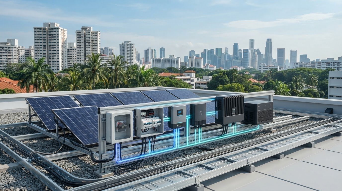
A solar array can generate power reliably and still fail to serve its loads if the distribution components don’t match. The term solar power distribution equipment covers hardware across different system scales and voltage levels, from DC-side protection and charge control to AC conversion and connection points. What moves power through a solar system, and how do the components fit together?
The answer depends on the project’s topology, loads and grid connection. Solar system distribution hardware manages power within the installation; utility distribution infrastructure is a separate part of the electricity network. Defining that boundary helps prevent mismatched specifications and incomplete equipment schedules.
This guide explains the functions and sequence of major components, then maps the DC-to-AC path for common system configurations. You’ll learn how panels, circuit protection, charge controllers, batteries and hybrid inverters fit together, and which interfaces need project-specific review. Use the guide to prepare an equipment schedule for technical review and procurement. SM Solar supplies solar hardware for off-grid and on-grid projects, including panels, batteries, controllers, protection devices and hybrid inverters.
Key Takeaways
- Separate solar power distribution equipment within a system from utility-scale transformers and medium- or high-voltage switchgear.
- Trace the power path from generation through control, protection, optional storage and conversion to loads or the grid.
- Compare grid-connected and off-grid priorities before building a bill of materials, because their equipment requirements differ.
- Use project documentation to record topology, loads, storage needs, electrical ratings, connection types and protection requirements.
- Match project needs to relevant hardware categories, including panels, charge controllers, batteries, circuit protection and roof mounting accessories.
What Solar Power Distribution Equipment Covers, and What It Does Not
Solar power distribution equipment is the hardware within a solar installation that routes, converts, controls, stores or protects electrical power between its source and intended loads or connection point. This system-level definition includes components that manage energy along the project’s electrical path. It does not mean every item in the wider electricity network belongs on the solar equipment schedule.
The scope depends on the project topology, intended loads, storage design and connection requirements. A stand-alone system supplying local loads has different interfaces from a grid-connected system that can export power. Build the equipment list from the documented design rather than starting with a generic package that assumes every installation needs the same components.
For a broad overview of how panels, inverters and other elements fit into stand-alone and grid-connected installations, see Photovoltaic System Components. The practical distinction is between hardware serving the solar installation and infrastructure serving the wider electricity network.
Which equipment belongs to a solar power distribution system?
Group components by their function. Panels generate electrical power. Charge controllers manage charging between a PV source and a battery where that arrangement is used. Batteries store energy, inverters convert DC power to AC where required, and circuit protection devices help protect electrical circuits. A system may include some or all of these categories, depending on its architecture and loads.
- Generation: Solar panels supply power to the system.
- Control and storage: Charge controllers and batteries serve designs that include battery charging and storage.
- Conversion and protection: Inverters provide DC-to-AC conversion where needed, while circuit protection is selected for the documented circuits.
This is a functional map, not a standard bill of materials. A project without battery storage won’t use the same component combination as one designed to store energy. In the equipment schedule, identify each component’s role and the interfaces it must support in the specific design.
How DC-side hardware differs from utility distribution equipment
DC-side solar hardware operates within the installation’s source, storage and load arrangement. Transformers and substations, by contrast, belong to the broader electrical network and may serve transmission or distribution functions beyond the solar array. Medium- or high-voltage switchgear, such as the medium-voltage equipment produced by manufacturers like Africa Switchgear & Transformers, is also network-level equipment, not another name for a solar circuit protection device.
The difference is one of role and scale. A circuit protection device is selected for a particular circuit in a solar system; a transformer changes voltage between parts of an electrical network. They serve different interfaces and aren’t interchangeable procurement categories. Depending on the project, utility infrastructure may connect to a solar installation at its grid interface. That does not make network equipment equivalent to the installation’s DC-side hardware.
To define the project scope, first set the solar system boundary: where generation enters, which equipment manages or converts power, whether storage is included, and where power is delivered. Then distinguish those components from any network-side equipment identified in the connection design. This keeps terminology precise and helps the equipment schedule reflect the actual topology, intended loads and connection requirements.
How Solar Distribution Equipment Moves Power Through a System
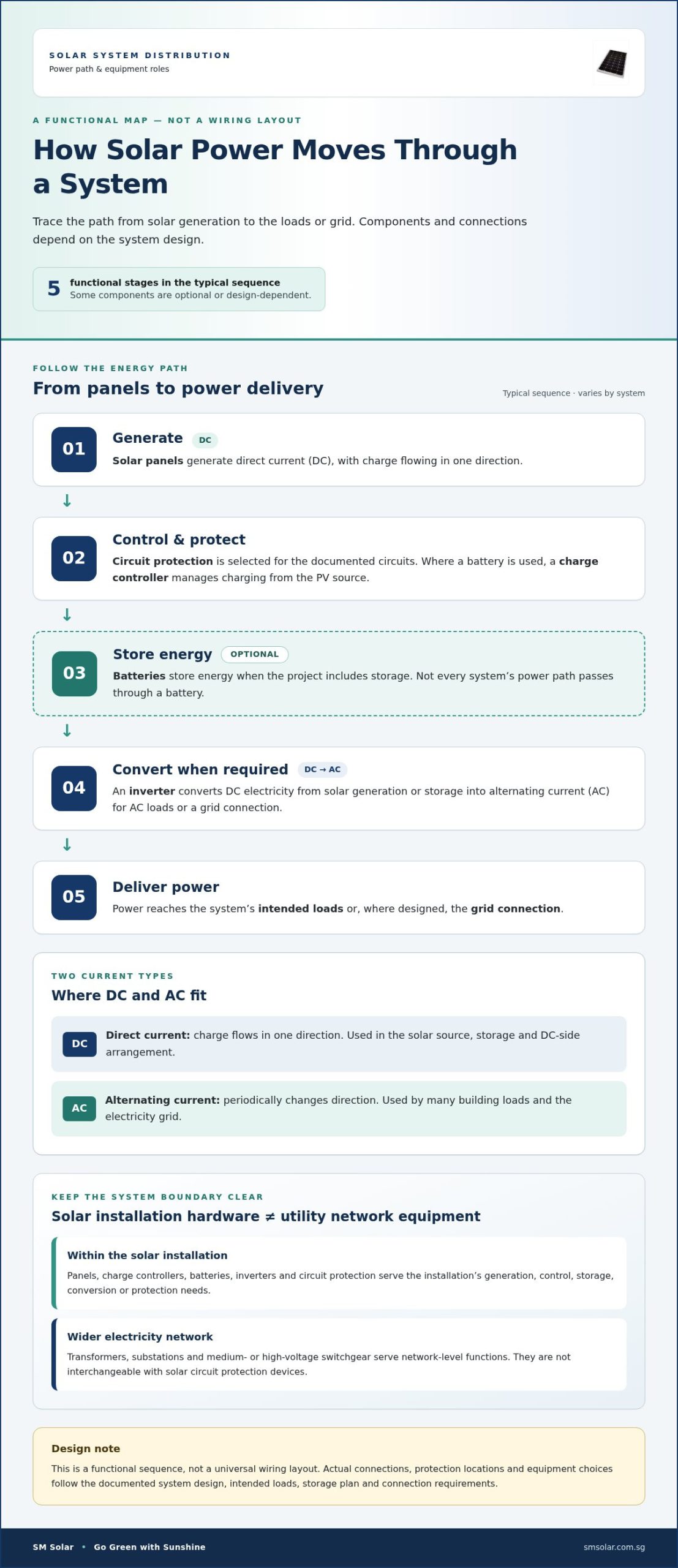
Follow the energy path to see how the components relate. Solar panels generate direct current (DC), in which charge flows in one direction. Alternating current (AC), used by many building loads and the electricity grid, periodically changes direction. Where included, a charge controller manages charging from the PV source to a battery. An inverter converts DC to AC when the design requires AC loads or a grid connection.
A typical functional sequence is generation, DC-side control and protection, optional storage, conversion where required, then delivery to loads or the grid. This describes the roles of solar power distribution equipment, not a universal wiring layout. Actual connections and protection locations follow the system design and verified project documentation.
From solar panels through charge control and storage
A charge controller regulates the relationship between the solar panels and a connected battery, managing charging within the designed system. A battery is included when the project calls for energy storage. Its position and connection depend on the system architecture, so not every panel-to-load path passes through storage.
Typical DC-side relationship where a battery is included:
Solar panels → DC-side protection and control → charge controller → battery → inverter or DC loads
This is a functional illustration, not installation instructions. Some systems use a different component arrangement or omit components that aren’t needed for their intended operation.
Where inverters and protection devices fit
An inverter converts DC electricity from solar generation or storage into AC electricity for AC loads. In a grid-connected design, the conversion equipment also forms part of the system’s interface with the grid. In an off-grid design, power is delivered to local loads, with storage included if the project requires it. The DOE Solar Energy Technologies Office discusses solar technology and grid integration, providing wider context on how a system can connect to the electricity network.
Protection devices may be needed at relevant circuit and equipment boundaries on the DC side, AC side or both. Their selection and placement depend on the project topology and documented electrical requirements. Don’t treat a simple diagram as a protection schedule or assume one layout applies to every system. For component-level detail, consult the existing solar circuit protection guide.
When preparing an equipment schedule, mark where generation enters, where control or storage occurs, where DC-to-AC conversion is needed, and whether power serves local loads, the grid or both. This makes interfaces clearer for technical review. Project teams sourcing panels, charge controllers, batteries, inverters and protection can also review SM Solar’s solar hardware range against their system design.
Grid-Connected and Off-Grid Equipment: Compare the Design Priorities
System topology determines where generated power can go and which equipment must manage that flow. A grid-connected system is designed to operate with an electricity network interface. An off-grid system serves loads without relying on that interface. Both use solar equipment, but their operating objectives differ. Treating them as interchangeable can leave a project schedule with components that don’t match the intended loads or operating conditions.
The comparison below shows typical design considerations, not mandatory equipment lists. Storage, conversion and control requirements depend on the project architecture. For grid-connected projects, base grid-interface requirements on the project documentation and applicable requirements rather than assumptions taken from another jurisdiction.
| Design consideration | Grid-connected system | Off-grid system |
|---|---|---|
| Power destination | Local loads and, where the design permits, the grid connection | Loads served within the standalone system |
| Storage role | Included when the project design calls for storage | Often considered to support operation when solar generation and load don’t coincide |
| Conversion | Inverter interfaces solar DC power with AC loads and the grid connection as designed | Conversion is selected to suit the required loads and system arrangement |
| Control considerations | Coordinate system operation with the defined grid interface and project requirements | Plan charge control, storage use and supply against the intended load profile |
Distribution priorities in grid-connected systems
In a grid-connected design, conversion equipment and the system interface support the movement of solar power to AC loads and the connection point. Storage may be included, but it isn’t an automatic requirement. Keep these general equipment functions separate from local interconnection rules, which depend on the project and market. Use project-specific documentation rather than applying standards or compliance assumptions from another jurisdiction as general guidance.
For the equipment schedule, identify the grid interface, intended loads and any storage provision. Then align component roles with those documented requirements. A component’s presence in another grid-connected design doesn’t establish that it belongs in this one.
Distribution priorities in off-grid systems
Off-grid planning centres on supplying defined loads without a grid connection. Charge control and battery storage feature in many such designs, but requirements depend on how and when loads operate and on the intended operating conditions. Record the load profile and storage objective before settling on the equipment combination. SM Solar supplies hardware for off-grid projects; these applications provide context, not proof of a particular system’s performance.
Select solar power distribution equipment against the project topology and load requirements, not a generic grid-versus-off-grid checklist. Review where power is needed, how the system will serve that demand, and which equipment functions the design actually requires. This gives technical reviewers a clearer basis for assessing component selection and interfaces.
How to Specify Solar Power Distribution Equipment for a Project
Build the equipment schedule from the project design, not from a standard product bundle. Before selecting solar power distribution equipment, establish the system topology, energy source, intended loads, storage requirements and operating conditions. Then use verified project documents to record electrical ratings, connection types and protection requirements. This ties component selection to actual interfaces and helps technical reviewers identify missing information.
Minimum selection inputs: topology, source, loads, storage objectives, operating conditions, documented electrical ratings, connection types and protection requirements.
Create an equipment schedule around system interfaces
Give each item a defined function and identify what it connects to. Record the source document for its requirements, such as the project design or equipment documentation. Make dependencies visible too: a controller must suit the designed panel-to-battery relationship, while battery and inverter interfaces must align with the intended storage and load arrangement.
| Schedule field | What to record |
|---|---|
| Component and function | Panel, charge controller, battery, inverter, or circuit protection device, with its role in the system |
| Electrical interface | Documented ratings and connection types for the relevant source, storage, load, or grid interface |
| Dependencies | Related components and design conditions that affect selection |
| Project reference | Drawing, specification, or other verified document supporting the recorded requirement |
Don’t fill gaps with assumed ratings or sizing rules. Flag missing values for technical review against the project documentation instead. This makes the schedule useful for procurement without treating a typical configuration as a universal specification.
Review protection, mounting and procurement details
Include circuit protection and relevant mounting accessories in the equipment schedule, even though they serve different functions. Protection items relate to electrical circuits and interfaces; pole mounts, roof clamps and brackets support panel mounting. Record the project basis for each selection. For device-specific considerations, refer to the solar circuit protection guide. For panel technology decisions, consult the monocrystalline solar panels technical overview.
Before procurement, compare the schedule with the system drawings and confirm that every listed component has a documented purpose, interface and requirement. Review dependencies across panels, controllers, batteries and inverters as a set. This helps expose mismatches before purchasing and provides a traceable basis for technical review.
For project teams assembling a schedule around solar hardware, review SM Solar’s solar equipment supply.
SM Solar’s Role in Supplying Solar Power Distribution Equipment
SM Solar is a wholesale distributor of solar hardware, with a core focus on 12 V DC solar products. For project teams building an equipment schedule, its portfolio covers key system functions: generation, charge control, storage, circuit protection, conversion and panel mounting. The right combination depends on the project design. It isn’t a fixed package that assumes every installation needs every component.
SM Solar was established in 2008 and became a private limited company in 2016. The company supplies hardware for off-grid and on-grid projects, giving project teams access to components for different system arrangements. Its company profile also lists clients for off-grid and on-grid projects. These examples provide project context, not a performance claim about any particular system.
A wholesale portfolio for solar project equipment
SM Solar’s product categories can be mapped to equipment schedule requirements:
- Generation: Monocrystalline solar panels.
- Charge control and storage: Solar charge controllers and batteries, including Lithium LiFePO4 batteries.
- Conversion: Hybrid inverters.
- Electrical protection: Solar circuit protection.
- Panel mounting: Solar panel pole mounts, standing seamlock roof clamps and roof mounting brackets.
These categories support different parts of a system, but the schedule should reflect the project’s topology, intended loads and documented interfaces. A design with storage has different component dependencies from one without it; mounting accessories also depend on the selected installation arrangement. As a wholesale hardware source, SM Solar supplies project teams assembling component schedules around defined requirements, rather than a one-size-fits-all bundle.
From equipment supply to project implementation
For end users, SM Solar also provides system integration, installation and after-sales maintenance. These capabilities extend beyond component supply to project implementation and ongoing support. The company’s listed off-grid and on-grid client projects show experience in both application contexts, without implying that one system configuration or equipment set suits every project.
For procurement planning, project teams can align the equipment schedule with the chosen system design, identify required categories and document interfaces for technical review. This creates a clearer basis for coordinating supply and integration requirements, whether the project is off-grid or grid-connected. SM Solar’s solar hardware portfolio includes panels, controllers, batteries, circuit protection, mounting accessories and hybrid inverters.
Discuss solar power distribution equipment for your project and its equipment supply and integration requirements with SM Solar.
Move Your Solar Project from Design to Procurement
Turn the project’s design intent into a coordinated procurement brief. Bring the system drawings, load requirements, storage objectives and documented equipment interfaces into one review. Resolve open technical decisions before preparing purchase orders, so each item has a defined role and a traceable project requirement.
A focused review also helps engineering and procurement teams work from the same component schedule. Together, they can identify dependencies and flag information that still needs technical resolution. This gives solar power distribution equipment selection a practical basis without relying on assumptions or generic packages.
For project teams planning equipment supply alongside implementation, SM Solar can support discussions about project requirements and integration needs. Discuss your solar project equipment requirements and take the next step toward a coordinated schedule.
With a clear brief and defined interfaces, your team can move forward with greater confidence.
Frequently Asked Questions
Is solar power distribution equipment the same as a distribution board?
No. Solar power distribution equipment refers to the wider set of components that manage electrical power in a solar installation; a distribution board is one possible board or assembly within a system. Terminology can vary between project documentation and electrical designs. A schedule may, for example, identify a specific board separately from an inverter or protection device. Use the project drawings and equipment schedule to identify the intended component rather than treating the terms as interchangeable.
Can an off-grid solar system operate without a battery?
Yes, some off-grid designs may supply loads while solar generation is available without storing energy in a battery. Whether that arrangement suits a project depends on when power is generated and when loads need it. If loads must be served when generation is unavailable, the design may require storage or another defined supply strategy. Compare the load profile with the intended operating conditions before deciding whether a battery belongs in the system.
What happens if an inverter cannot support the connected AC loads?
The system may not operate the connected equipment as intended, but the specific result depends on the inverter and load characteristics. Check the inverter’s documented ratings against the loads and their operating requirements using project documentation. For example, the schedule should account for every AC load the design expects the inverter to serve, not just the equipment’s general category. Resolve any mismatch during design review rather than assuming a particular fault will occur.
Does every solar system need a combiner box?
No. A combiner box is not a universal requirement; whether it belongs in a design depends on the PV configuration, string arrangement and electrical design. A project with a different array layout may use a different arrangement. Don’t add one solely because it appears in another system’s equipment list. Refer to the system drawings and applicable project requirements to determine the intended configuration, without treating this answer as a wiring prescription.
Can solar distribution components from different manufacturers work together?
Potentially, but manufacturer names alone don’t establish compatibility. The relevant electrical ratings, connection interfaces, operating requirements and overall system design must align. For example, review the documented relationship between a charge controller and battery, as well as the interfaces between the inverter and connected equipment. Assess the equipment documentation and system schedule together. Without supporting technical information, don’t assume a particular combination is approved or suitable.
What information should a project team provide when sourcing solar distribution equipment?
Provide the system topology, intended loads, storage requirements, component interfaces and operating conditions, along with relevant drawings and specifications. These inputs help define a coherent equipment schedule and support technical review. For instance, clarify whether the system is grid-connected or off-grid and identify the equipment the design is intended to serve. SM Solar supplies solar hardware and provides system integration capabilities for projects requiring equipment coordination.

