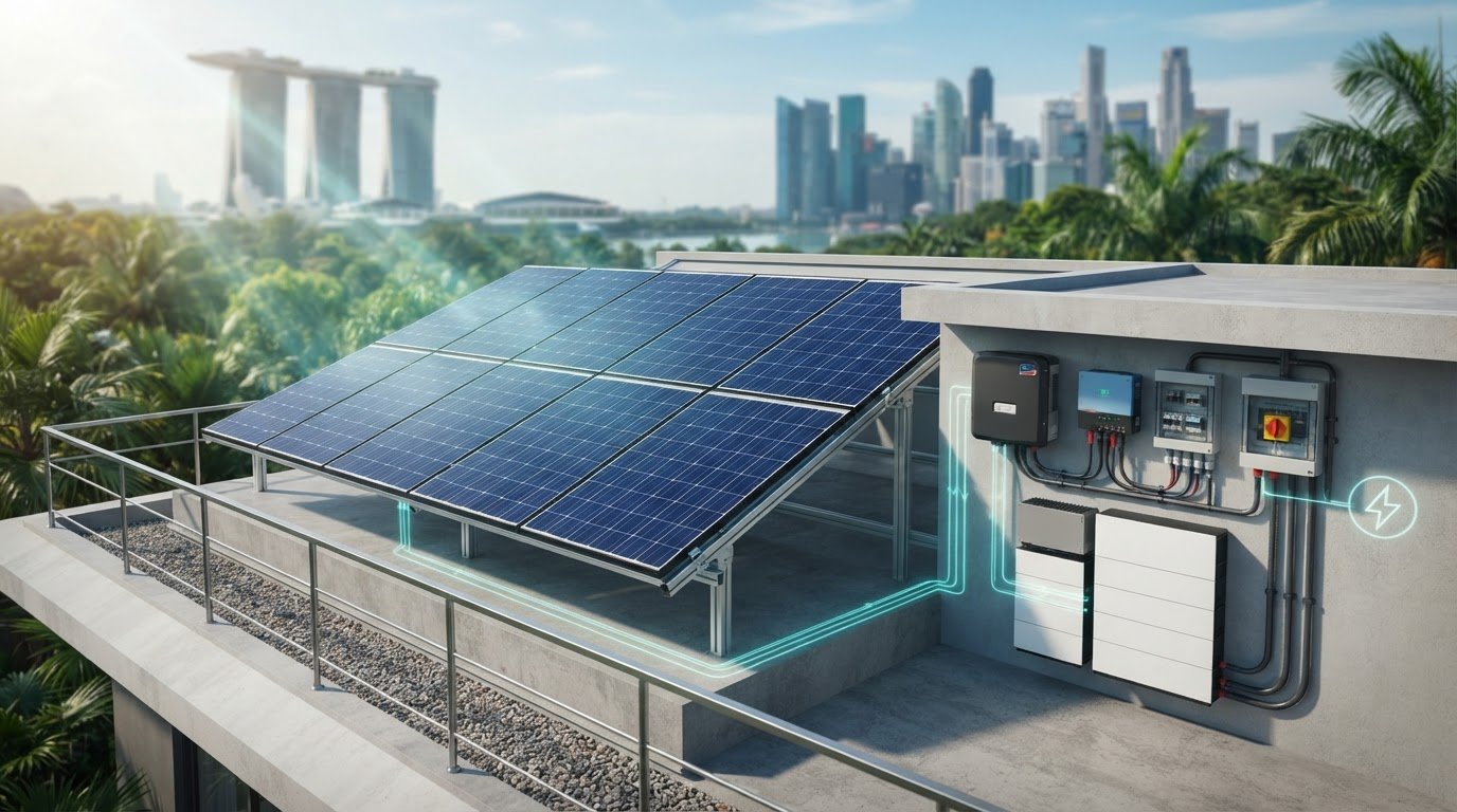
What if the right solar panel still couldn’t make a system work? Photovoltaic system components must operate as a compatible electrical chain, not as a list of independently selected parts. Identifying panels, inverters, batteries and protection devices is straightforward. The harder task is tracing how power moves between them and checking that their electrical and mechanical interfaces match.
This guide explains the main hardware groups and how they work together, from panel-generated DC power to conversion for loads or a grid connection. System architecture depends on project requirements: a grid-connected design may not need storage, while an off-grid or battery-backed system adds storage and associated control functions. Learn where solar charge controllers, hybrid inverters, LiFePO4 batteries, circuit protection and mounting hardware fit, and which compatibility points to review. Use the guidance to assess requirements and plan component sourcing alongside system integration.
Key Takeaways
- Identify the main photovoltaic system components by role, from generation and conversion to protection, mounting and optional storage.
- Trace the power path through the system architecture and note where charge control and batteries fit when storage is required.
- Assess compatibility by mapping each component’s upstream and downstream interfaces, electrical side and function.
- Turn project requirements into a component plan by defining loads, selecting a topology and separating confirmed inputs from assumptions that need engineering review.
- SM Solar supplies solar hardware and provides system integration capabilities, with a core focus on 12 V DC solar products.
What Components Make Up a Photovoltaic System?
Photovoltaic system components are the coordinated electrical and structural hardware used to generate, convert, protect, mount and, where required, store solar energy. The combination depends on how a project supplies loads and whether it connects to the grid, uses DC loads, includes batteries or combines these functions. A component list is only a starting point: each item has a specific role and interfaces with other parts of the system.
Electrically, a system may include a direct-current (DC) path from the panels and an alternating-current (AC) path for compatible loads or a grid connection. The inverter, battery arrangement and charge-control equipment depend on the chosen topology, so not every system contains the same devices. Group the components of a photovoltaic system by their role in the energy path, then consider the structures that support the panels separately.
Generation and power-conversion components
Solar panels, also called PV modules, generate electricity by converting sunlight into DC power. Modules connect into an array, whose output feeds the next stage of the design. Monocrystalline solar panels are one type of panel used in PV systems.
An inverter converts DC electricity into AC when the system supplies AC loads or interfaces with an AC network. A hybrid inverter can combine conversion and system-management functions, depending on its design and the system arrangement. In systems that charge batteries directly from a DC source, a solar charge controller regulates the charging connection between the PV array and battery. Its role differs from an inverter, although a system may use both.
Storage, protection, and mounting components
Batteries store energy for later use when storage is part of the project. A battery, such as a lithium LiFePO4 unit, needs to be considered as part of the system design, not added without checking how it connects to the other equipment. Circuit protection devices are selected and placed according to the circuits they protect and the points that require isolation.
Mounting hardware has a structural role: it secures panels to a suitable support surface or structure. It does not generate, convert or store electricity. Choose the mounting method to suit the installation arrangement.
- Electrical components: PV modules, inverters, charge controllers, batteries and circuit protection devices.
- Structural accessories: Roof clamps, mounting brackets and pole mounts.
For example, a roof-mounted array may use roof clamps or brackets, while a pole-mounted array uses pole-mount hardware. Account for both the electrical design and the mounting arrangement, but treat them as separate requirements. Keeping these categories distinct makes it easier to identify each item’s function before checking how its interfaces fit with the system.
How Photovoltaic System Components Connect Across Different Architectures
A PV system’s architecture determines how electricity moves from generation to the point of use. The general path starts at the PV modules, continues through conversion or charge-control equipment as required, and reaches loads through the system’s distribution arrangement. Storage adds another route for energy, while a grid connection provides an interface with the utility network. This sequence explains component roles, but it is not a wiring diagram: exact connections depend on the chosen topology and project specifications.
Grid-connected and hybrid system pathways
In a grid-connected arrangement, PV modules supply DC electricity to an inverter, which converts it to AC for compatible loads and the system’s grid interface. The inverter’s position and functions depend on the design. Distribution equipment routes power within the system. A grid connection does not mean every load is supplied in the same way, or that all systems use identical inverter and protection arrangements.
A hybrid arrangement can coordinate PV generation, grid connection and battery storage. Depending on its design, a hybrid inverter manages conversion and energy flow between connected parts of the system. The battery stores energy, while the grid remains another system interface. Because configuration and energy pathways vary, the term “hybrid” alone does not specify the wiring or how the system prioritises power.
- Grid-connected: PV generation is converted for AC-side loads and connection to the grid. Battery storage is not inherent to this arrangement.
- Off-grid: The system supplies designated loads without relying on a grid connection as its normal supply path.
- Hybrid: PV, storage and a grid connection can be coordinated within one architecture, subject to the equipment design.
Off-grid systems and DC-side coordination
In a battery-charging design, PV modules feed a charge controller, which manages the charging connection to the battery. The battery can then supply DC loads through the system’s distribution and protection equipment. If the project includes AC loads, an inverter converts DC power for those loads. This creates distinct DC and AC sections, each with its own equipment and interface requirements.
DC-side coordination means matching the PV input, charge control, battery arrangement, protection and intended loads as a system. A 12 V DC design is one possible context, not a universal specification for off-grid systems. SM Solar focuses on 12 V DC solar products, and the project architecture should still reflect its requirements and selected equipment.
Before selecting hardware, list each intended load by supply type and trace its proposed power path back to the PV array or storage. This makes conversion and charge-control needs visible early. SM Solar supplies solar components and system integration, including panels, controllers, batteries and circuit protection. Final wiring and equipment selection should follow the designed topology and project specifications.
How to Assess Compatibility Between Photovoltaic System Components
Compatibility is a system-level check, not a brand-name match. A component can suit its individual task yet still be a poor fit for the architecture or an adjacent device. Assess its function, the system topology, its electrical side and the project requirement separately. Then compare each interface with the actual equipment datasheets and design documentation.
A simple interface matrix can expose gaps before components are specified or sourced:
- PV modules: Upstream interface: sunlight and array configuration. Downstream interface: inverter or charge-control input. Compare module output characteristics with the connected equipment’s permitted input range.
- Charge controller: Upstream interface: PV array. Downstream interface: battery. Check that the controller’s input and battery-charging specifications align with the array and battery design.
- Battery: Upstream interface: charging equipment. Downstream interface: DC loads or inverter, according to topology. Review chemistry, system voltage and stated operating limits.
- Inverter: Upstream interface: PV, battery or both, depending on type and design. Downstream interface: AC distribution and loads. Match its input requirements and output characteristics to the system plan.
- Protection devices: These connect to the circuits they protect. Check their ratings and specified installation position against the circuit design.
- Mounting hardware: This connects the panel to its supporting structure. Confirm that the attachment method suits the roof or pole arrangement and the relevant component specifications.
Check electrical interfaces and operating requirements
Start with the module datasheet. Compare its voltage and current characteristics with the connected inverter or charge controller, including the equipment’s stated operating limits. Nominal voltage alone is not enough: array configuration and operating conditions affect the values presented to downstream equipment. Check power ratings and use the equipment documentation to confirm that the proposed combination falls within its specified range.
For battery charging, confirm that the charging equipment supports the battery chemistry and system voltage specified for the project. Review the battery’s charging requirements alongside the controller or inverter documentation. Protection-device selection also depends on circuit context. Verify ratings and placement against the design instead of treating devices as interchangeable because they serve the same broad function.
Match mounting hardware to the installation structure
Identify the roof type or pole-supported arrangement before selecting structural accessories. Standing seam roof clamps are intended for standing-seam attachment; roof mounting brackets suit roof-mounting arrangements where the specified interface fits. Pole mounts support pole-mounted configurations. These categories alone do not establish compatibility. Compare the panel attachment points, support structure and accessory documentation for the planned installation.
Record the results in the matrix and reference the relevant datasheet or design detail. Mark unresolved values for engineering review rather than assuming that similar names, nominal ratings or physical appearance prove compatibility. This creates a traceable basis for comparing photovoltaic system components and identifying interfaces to resolve before procurement.

How to Translate Project Requirements Into a Component Plan
Build the component plan from the project brief. Define what the system must supply, identify its architecture, then map each requirement to hardware and interface information. This keeps confirmed inputs separate from assumptions that need engineering review and gives procurement and technical teams a shared schedule to work from.
Build the system brief before specifying hardware
Record the load type and operating profile first: which equipment needs power, whether it uses DC or AC, and when it operates. Note whether the project has a grid connection, requires battery storage or is designed around DC equipment. Add installation constraints, including the intended mounting arrangement. If a load profile, connection detail or site condition is unknown, mark it as an open input rather than filling the gap with an assumption.
- Define loads. Record load type, supply type and operating profile. Separate confirmed requirements from missing information.
- Select topology. Establish whether the project is grid-connected, off-grid or hybrid, and whether storage is required.
- Establish interfaces. Identify DC and AC connections, equipment boundaries and structural attachment points that the design must accommodate.
- Map hardware categories. Assign components to generation, conversion, storage, protection and mounting, then note which specifications still need technical review.
This brief helps distinguish primary requirements from optional design choices. For example, a DC-centred project and a project supplying AC loads may need different conversion equipment. Reflect that distinction in the component plan rather than assuming every topology uses the same equipment sequence.
Create a component schedule for technical review
Organise the schedule by function, keeping electrical equipment separate from structural accessories. For each item, record its role, upstream and downstream interfaces, relevant datasheet fields, and whether the information is confirmed or needs review. This makes gaps visible before sourcing and gives the team a basis for checking the selected photovoltaic system components as a coordinated set.
- Generation: List PV modules, array configuration and module output fields. Use this monocrystalline solar panel technical overview for module-specific context.
- Conversion and control: Record the inverter or charge-controller function, connection points and applicable input or output requirements.
- Storage: If included, document battery chemistry, system voltage and charging interface. The guide to LiFePO4 battery storage provides related context.
- Protection: Identify circuit locations and device requirements. Refer to the guide on solar circuit protection devices when developing this schedule section.
- Mounting: List roof clamps, brackets or pole mounts separately, with the intended structure and attachment interface.
Mark unresolved design values for engineering review. Use this structured component plan to discuss solar hardware and system integration with SM Solar.
How SM Solar Supports Photovoltaic Component Supply and Integration
SM Solar is a wholesale distributor of photovoltaic hardware and provides system integration, installation and after-sales maintenance for end users. These capabilities connect component supply with project-level planning. The company’s core product focus is 12 V DC solar products.
Component categories within SM Solar’s supply range
SM Solar’s supply range covers electrical hardware and supporting accessories used in different parts of a PV system. The categories below describe component roles, not individual model specifications. Project teams can use them to organise a component schedule before reviewing equipment interfaces and datasheets.
- Generation: Solar panels, including monocrystalline panels, provide the PV generation hardware.
- Control and conversion: Solar charge controllers and hybrid inverters support system arrangements that require charge control or power conversion.
- Storage: Lithium LiFePO4 batteries and other solar battery categories support designs that include energy storage.
- Electrical protection: Solar circuit protection devices form part of the system’s electrical hardware plan.
- Mounting and accessories: Standing seamlock roof clamps, roof mounting brackets and solar panel pole mounts support different structural arrangements. Other DC-related products are also part of the supply range.
Specify these categories against project requirements rather than treating them as a pre-set package. The solar energy equipment supplier guide provides related context for organising equipment requirements and planning supply.
From hardware supply to system integration
Component supply addresses the hardware list; system integration considers how the selected equipment fits within the project architecture. SM Solar provides system integration and installation, as well as after-sales maintenance for end users. These capabilities support a broader project scope while allowing the equipment configuration to reflect each system’s requirements.
SM Solar’s client list includes 10 off-grid system clients and 5 on-grid system clients. This reflects work across both architecture types. Each project’s component plan still depends on its defined loads, topology, interfaces and installation requirements. The practical benefit is a connected view of component categories and their roles within an integrated system.
For a clear review, prepare the project’s load and topology information, identify the required component categories, and record unresolved interface or specification questions. SM Solar can support project teams with solar component supply, system integration, installation and after-sales maintenance for end users.
Move From Component Plan to Project Review
Turn your component schedule into a project-ready sourcing brief. Record the intended architecture, required hardware categories and unresolved technical inputs together, so the review can focus on system fit rather than isolated product choices. This gives your team a clearer basis for coordinating specifications and procurement as the design develops.
SM Solar was established in 2008. Use your project brief to connect requirements with the relevant photovoltaic system components and integration support. A structured review keeps sourcing decisions aligned with the intended configuration.
Review SM Solar’s photovoltaic component range and discuss your system integration requirements.
Frequently Asked Questions
Can photovoltaic system components from different manufacturers work together?
Yes. Components from different manufacturers can work together if their electrical and mechanical interfaces are compatible. Compare datasheet values, connector specifications, communication requirements where applicable, and operating limits. For example, a panel and inverter may have suitable nominal ratings but still need to be checked against the inverter’s permitted input range. Keep the relevant datasheets and compatibility decisions with the project documentation for future maintenance or replacement.
Can a photovoltaic system power DC equipment directly?
Yes, a PV system can supply DC equipment if its voltage and current requirements suit the designed DC supply. Panel output varies with operating conditions, so a direct connection is not automatically appropriate. A regulated supply, charge controller or battery arrangement may be needed to provide the required electrical conditions. Check the load specifications and system design before connecting equipment, especially if its operation depends on stable voltage.
Are solar mounting components considered electrical components?
No. Mounting components are structural accessories, not electrical devices. Their role is to attach and support the modules within the chosen installation arrangement. Roof clamps, mounting brackets and pole mounts address different structural interfaces. They still affect system planning because the panel and support arrangement must fit together, but they do not perform electrical conversion, storage or circuit protection. Keep them in a distinct section of a bill of materials.
Can individual photovoltaic components be replaced without replacing the whole system?
Often, an individual component can be replaced, but the replacement must suit the existing system. First identify the failed or obsolete item and document its connections, ratings and role. Then compare the replacement’s specifications with adjacent equipment and the system design. A change to an inverter, battery or controller can affect other interfaces, so include a technical review rather than relying on physical fit alone.
What information should a photovoltaic component schedule include?
A useful schedule identifies each item, its function, position in the system, upstream and downstream connections, and the source of its specification data. Include model identifiers once selected, relevant voltage, current and power fields, and mounting or attachment details where applicable. Mark each value as confirmed, pending or subject to engineering review. This makes procurement gaps visible and gives installers and maintenance teams a shared reference.
How do DC and AC components differ in a photovoltaic system?
DC components operate on the direct-current side, which may include PV modules, battery connections and DC loads. AC components serve alternating-current circuits, such as compatible loads supplied through an inverter. The distinction matters because equipment ratings, protection and connection methods depend on the circuit type. An AC load may require conversion from a DC source, while a suitable DC load may be served on the DC side.
Does every photovoltaic system need a battery and charge controller?
No. A grid-connected system can be designed without battery storage, and a charge controller is generally relevant when the design includes controlled charging of a battery from a DC source. Equipment configuration depends on the system topology and selected inverter or charging arrangement. Before specifying either item, establish whether the project requires stored energy and how the battery will connect to the rest of the system.