Tag: LFP battery

  • LFP Battery Technology Guide: Engineering Specifications, Chemistry, and Industrial Storage Integration

    LFP Battery Technology Guide: Engineering Specifications, Chemistry, and Industrial Storage Integration

    High volumetric energy density delivers zero commercial value if sustained ambient heat degrades your stationary storage asset years before it yields a return. For industrial solar engineering projects, the lfp battery has established itself as the standard architecture over volatile nickel-rich chemistries and high-maintenance lead-acid alternatives.

    Verifying true cycle-life ratings across variable depths of discharge remains a persistent operational challenge, particularly when high ambient operating temperatures and passive BMS balancing limitations threaten premature cell failure. You need verified electrochemical thresholds and consistent operational performance rather than speculative laboratory datasheets. This technical guide delivers a rigorous analysis of lithium iron phosphate cell chemistry, degradation pathways, and integration standards for stationary energy storage.

    We’ll examine the core parameters that distinguish LFP cells from competing chemistries, establish exact charge and thermal thresholds to maximize longevity, and specify the hardware requirements for pairing high-capacity battery racks with industrial hybrid inverters and protective DC switchgear.

    Key Takeaways

    • Understand how the stable olivine crystal lattice prevents structural breakdown and elevates the thermal runaway threshold above conventional oxide chemistries.
    • Evaluate verified lfp battery cycle longevity across standard depth-of-discharge profiles while configuring optimal continuous and peak C-rates for stationary loads.
    • Mitigate ambient heat degradation and condensation risks specific to tropical operating environments through verified thermal management and enclosure protection standards.
    • Calculate precise DC operating voltage windows to ensure electrical compatibility and direct communication with commercial hybrid inverters.
    • Specify coordinated DC circuit protection and battery management parameters to eliminate cell balancing faults and safeguard balance-of-system hardware.

    Electrochemical Structure and Operating Principles of the LFP Battery

    The lithium iron phosphate cell relies on an ordered olivine crystal framework (triphylite structure) belonging to the space group Pnma. In a standard commercial lithium iron phosphate battery, the positive electrode utilizes LiFePO4 as the active material, coupled with a synthetic graphite anode (C) across an organic carbonate electrolyte containing dissolved LiPF6 salt. During charge and discharge operations, charge transport proceeds through a single-phase and two-phase delithiation process:

    LiFePO4 ↔ FePO4 + Li+ + e-

    Individual cells feature a nominal potential of 3.2V DC. The usable electrochemical operating window spans from an upper charge cut-off of 3.65V down to a lower discharge limit between 2.50V and 2.00V. For stationary storage racks, designers avoid these extremes to mitigate structural degradation, targeting a functional cycle threshold between 2.80V and 3.45V per cell.

    The LiFePO4 Crystal Matrix and Chemical Bond Stability

    The primary advantage of the olivine matrix lies in the strong covalent bonding within tetrahedral phosphate units (PO4)3-. Oxygen atoms are tightly bound to phosphorus via robust P-O covalent bonds, preventing oxygen release during high-rate charging, deep cycling, or continuous mechanical stress. In contrast to the planar cobalt-oxide sheets found in NMC cells, the three-dimensional olivine framework retains rigid structural integrity under extreme electrical loads without collapsing or venting oxidizers.

    Nominal Voltage Characteristics and Charge-Discharge Profiles

    LFP chemistry exhibits an exceptionally flat discharge curve between 20% and 80% state of charge (SoC). Over this core operational range, cell voltage fluctuates by less than 100 millivolts, maintaining a steady 3.20V to 3.25V output under typical stationary discharge rates.

    • Voltage-Based Monitoring Challenges: Voltage readings alone cannot determine remaining capacity during steady-state cycling. Battery management systems (BMS) must utilize continuous Coulomb counting alongside active shunt current measurement.
    • OCV Settling Protocols: Open-circuit voltage (OCV) requires significant rest periods, often 30 to 120 minutes without current flow, to stabilize and allow the BMS to reset state-of-charge calculation drift.
    • Top-End Balancing Requirements: Because cell voltage diverges rapidly only above 3.40V and below 3.00V, accurate balancing must occur strictly during the final charge absorption phase.

    This tight operational window requires precise voltage calibration across multi-cell strings. Industrial storage racks rely on coordinated BMS protocols to preserve uniform state-of-charge tracking across thousands of continuous operational hours.

    Core Technical Specifications: Cycle Life, C-Rates, and Thermal Thresholds

    Stationary industrial storage demands predictable duty cycles across multi-decade operational horizons. A commercial lfp battery bank operates reliably at continuous discharge rates of 0.5C to 1C, handling transient peak loads up to 2C depending on busbar sizing and rack thermal management. For sustained charging, limiting input to 0.5C or lower minimizes localized resistance heating and limits internal mechanical strain on the cathode particles.

    Cycle Life Longevity vs. Operational Depth of Discharge (DoD)

    Cell degradation trajectories closely track operational discharge depths. Discharging to 100% DoD daily accelerates solid electrolyte interphase (SEI) layer growth on the graphite anode, restricting expected lifespan to approximately 2,500 to 4,000 cycles before capacity drops to 80% of its initial rating. Setting a functional threshold of 80% DoD expands service delivery to between 3,500 and 6,000 cycles.

    System integrators can optimize asset life by adjusting charge cutoff parameters. Capping single-cell charging at 3.45V rather than the chemical ceiling of 3.65V prevents high-potential electrolyte decomposition without sacrificing usable capacity. Engineering teams designing high-throughput installations can source compatible cell blocks via lithium LiFePO4 batteries built to maintain structural equilibrium across thousands of high-depth discharge sequences.

    Thermal Runaway Resistance and Temperature Tolerance

    Safety parameters distinguish LFP from oxide-based chemistries during severe electrical or environmental stress. The thermal runaway onset temperature for an lfp battery sits at approximately 270°C, compared to roughly 210°C for nickel-manganese-cobalt (NMC) configurations. Because the covalent phosphate framework resists releasing elemental oxygen, the cell prevents self-accelerating combustion cycles during internal short circuits.

    • Sub-Zero Regimes: Charging at temperatures below 0°C induces metallic lithium plating on the negative electrode. This causes permanent capacity fade and creates internal micro-dendrites. BMS programming must disable charge currents whenever core temperatures fall below freezing.
    • Elevated Thermal Exposure: Ambient operational limits typically extend to 55°C. Sustained exposure above 35°C accelerates calendar aging via parasitic chemical reactions, though the absence of oxygen generation allows safe operation in warm environments without requiring pressurized liquid chilling loops.

    LFP vs. Alternative Chemistries: NMC, Lead-Acid, and Industrial AGM

    Selecting stationary energy storage chemistry requires balancing volumetric footprint against cycle longevity, thermal behavior, and structural load constraints. Automotive propulsion systems prioritize pure gravimetric density to extend vehicle range. Stationary industrial deployments prioritize operational safety, structural simplicity, and lowest lifecycle degradation.

    LFP versus NMC: Safety, Cost, and Energy Density Trade-Offs

    Nickel-manganese-cobalt (NMC) cells provide superior energy density, reaching 200 to 250 Wh/kg at the pack level compared to 160 to 190 Wh/kg for an industrial lfp battery. However, stationary commercial installations rarely have the strict weight limits that justify NMC safety liabilities. In occupied commercial and industrial facilities, NMC installations require complex liquid cooling loops, stringent physical separation barriers, and high-output fire suppression systems to comply with modern stationary storage standards like NFPA 855.

    Supply chain security presents another operational divergence. Eliminating cobalt and nickel shields LFP production from volatile commodity price spikes and constrained extraction pipelines. Sourcing relies on abundant iron and phosphate precursors, ensuring continuous component availability for large-scale engineering rollouts.

    LFP versus Industrial AGM: Operational Efficiency and Floor Load

    Replacing deep-cycle Absorbent Glass Mat (AGM) or traditional lead-acid banks with an lfp battery resolves major structural and electrical inefficiencies in stationary facilities:

    • Usable Capacity: Deep-cycle AGM strings require a strict 50% depth-of-discharge limit to reach a nominal 500 to 1,000 cycles. LFP banks run continuously at 80% to 90% DoD, providing double the usable capacity from identical nominal storage ratings.
    • Round-Trip Efficiency: LFP delivers roughly 95% round-trip electrical efficiency, whereas AGM configurations lose 15% to 20% of stored energy to internal heat during charge-discharge cycles. This 10% to 15% efficiency gap lowers parasitic thermal loads on power-room HVAC infrastructure.
    • Civil Floor Loading: Lead-acid installations impose extreme static floor loads that often necessitate structural reinforcement of building slabs. LFP cuts battery mass by up to 70%, allowing high-density multi-tier rack integration on standard industrial floors.
    • Ventilation Requirements: AGM systems produce explosive hydrogen gas during float and boost charging phases, requiring dedicated mechanical extraction systems. Sealed LFP racks release zero hydrogen during standard cycling, simplifying facility air handling and permitting.

    LFP Battery Technology Guide: Engineering Specifications, Chemistry, and Industrial Storage Integration

    Engineering Considerations for Tropical Solar Storage in Singapore and Malaysia

    Tropical installations across Singapore and Malaysia present severe environmental stressors for stationary storage. Year-round ambient temperatures frequently exceed 32°C, paired with relative humidity levels consistently above 80%. When deployed in unconditioned outdoor enclosures, unmanaged internal rack temperatures can quickly surpass 40°C. Operating an lfp battery continuously above 35°C accelerates electrolyte decomposition, expediting capacity fade despite the chemistry’s baseline thermal stability.

    Thermal Management and Enclosure Ventilation Protocols

    Enclosure design must prioritize passive heat rejection to maintain internal cell cores below 35°C. Rack-mounted battery modules require a minimum vertical clearance of 1U to 2U (44.45 mm to 88.9 mm) between chassis to facilitate convective airflow across integrated aluminum heat sinks.

    For outdoor cabinets, ingress protection must meet minimum IP65 standards to prevent tropical moisture penetration. High humidity combined with diurnal temperature swings creates severe internal condensation risks during inverter load transitions. Integrators must incorporate thermostatically controlled PTC anti-condensation heating elements alongside closed-loop heat exchangers. This design preserves sealed IP65 isolation without pulling humid, saline ambient air across sensitive DC busbars.

    BMS Architecture and Mandatory Electrical Protection

    Maintaining pack-level equilibrium in tropical climates requires battery management system (BMS) architecture with cell-level active balancing. Sustained ambient heat amplifies minor manufacturing variances in internal cell resistance, accelerating state-of-charge drift over time. BMS hardware must link directly to plant controllers and hybrid inverters via isolated CAN bus 2.0B or RS485 Modbus RTU communication protocols, delivering real-time cell voltages, thermal sensor telemetry, and dynamic charge-current limits.

    DC protection schemes demand high interrupt ratings. Because an industrial lfp battery bank exhibits exceptionally low internal impedance, potential short-circuit fault currents can exceed 20 kA. Installations require fast-acting Class T or high-speed semiconductor fuses paired with polarized DC molded-case circuit breakers (MCCBs) for galvanic isolation. To ensure total operational compliance, source industrial solar circuit protection engineered to clear high prospective fault currents under regional standards like MS IEC 62619 and Singapore Standard SS 637.

    System Integration: Inverter Matching, DC Protection, and Hardware Sourcing

    Connecting an lfp battery bank to commercial balance-of-system hardware requires strict coordination between inverter MPPT inputs, charge controllers, and DC busbar ratings. A standard low-voltage nominal 48V bank (16S configuration) operates between 44.8V (discharge floor) and 58.4V (charge ceiling). High-voltage commercial strings stack series cells to reach 200V to 800V DC bus windows, reducing continuous current requirements and conductor mass across high-capacity facilities. Sizing must match continuous battery discharge capacity to the peak conversion demand of the inverter while buffering incoming solar charge controller output.

    Safe commissioning follows a strict hardware sequence: structural rack anchor placement, torque-verified busbar terminal connections, DC overcurrent protection installation, BMS communication handshake validation, and pre-charge circuit engagement to eliminate inverter capacitor inrush currents.

    Hybrid Inverter Voltage Window and Charge Parameter Calibration

    Inverter firmware settings govern operational lifespan. For standard 16S packs, configure bulk and absorption stages to 55.2V (3.45V per cell) rather than the chemical maximum of 58.4V. This adjustment preserves usable capacity while eliminating high-voltage trip events. Set float voltage to 53.6V (3.35V per cell) to offset self-discharge without accelerating calendar fade.

    System designers must prioritize closed-loop CAN bus integration over open-loop voltage sensing. Closed-loop controls allow the internal BMS to command real-time current limits directly from hybrid inverters based on dynamic cell temperatures and pack state-of-charge. Open-loop schemes rely solely on gross busbar voltages, leaving the installation vulnerable to nuisance BMS disconnections during sharp solar irradiance fluctuations.

    Balance of System Procurement and Wholesale Sourcing Framework

    Industrial storage reliability depends on engineering alignment across the entire mechanical and electrical assembly. Rooftop PV installations utilizing standing seamlock roof clamps and monocrystalline solar panels must deliver generation curves tailored to the charge acceptance metrics of the stationary battery array. Procuring balance-of-system equipment through SM Solar provides EPCs with fully compatible hybrid inverters, certified lithium LiFePO4 batteries, and calibrated solar circuit protection hardware from an established regional supply chain.

    Deploying Resilient LFP Architecture for Long-Term Storage

    Executing a dependable stationary storage installation requires rigorous adherence to electrochemical constraints. The intrinsic safety of the olivine lattice establishes the lfp battery as the optimal standard for tropical commercial operations, resisting thermal runaway even under high sustained ambient temperatures. Achieving rated cycle lifespans requires disciplined engineering: conservative voltage cutoffs, responsive closed-loop BMS communication, and robust ingress protection.

    Component compatibility across the direct current bus determines real-world system reliability. Engineering procurement teams must eliminate hardware mismatches between battery racks, power conversion units, and DC overcurrent devices. As a regional wholesale distributor established in 2008, SM Solar maintains direct inventory of industrial-grade storage hardware across Singapore and Malaysia. Source Commercial LFP Batteries and Solar Hardware at SM Solar to secure fully matched LiFePO4 batteries, commercial hybrid inverters, and coordinated DC circuit protection for your upcoming projects.

    Frequently Asked Questions

    What is the typical operating life expectancy of an LFP battery in stationary solar storage?

    In stationary applications, high-grade LFP cells typically deliver between 3,500 and 6,000 full cycles when cycled daily at 80% Depth of Discharge (DoD) before reaching 80% retained capacity. Under standard cycling conditions of one cycle per day, this translates to a functional operating lifespan of 10 to 15 years. Longevity depends directly on operating temperature, charging current limits, and avoiding extended rests at full charge.

    Can an LFP battery suffer from thermal runaway under operational stress?

    Thermal runaway is rare in an lfp battery due to the strong covalent phosphate bonds, but it isn’t impossible under catastrophic abuse. Thermal runaway onset requires core temperatures around 270°C, which is far higher than nickel-based alternatives. Sustained mechanical puncture, continuous excessive overcharging without BMS intervention, or external fire can trigger exothermic venting, though the cells don’t release free oxygen to fuel runaway combustion.

    Why is a dedicated Battery Management System (BMS) mandatory for every LFP bank?

    A dedicated BMS is critical because LFP chemistry cannot self-balance during overcharge, unlike lead-acid batteries that convert excess current into heat or gas. Overcharging an LFP cell above 3.65V causes rapid electrolyte decomposition, while discharging below 2.00V causes permanent anode damage. The BMS monitors individual cell voltages, tracks temperature, enforces safe charge limits via closed-loop inverter communication, and disconnects the DC busbar during fault conditions.

    How does ambient tropical heat affect LFP battery degradation and round-trip efficiency?

    Ambient temperatures above 32°C in Singapore and Malaysia accelerate parasitic reactions at the electrolyte interface, increasing SEI layer growth and reducing overall calendar life. While elevated heat slightly improves internal ion mobility and lowers initial internal resistance, continuous high-temperature cycling causes premature capacity fade. Round-trip efficiency remains relatively stable near 95%, but long-term capacity retention drops unless enclosures feature adequate ventilation or heat exchangers.

    Can LFP batteries directly replace AGM lead-acid batteries without changing the solar inverter?

    Direct replacement is possible only if the existing solar inverter allows custom charging voltage setpoints. Standard lead-acid charging curves utilize multi-stage algorithms with temperature compensation and desulfation stages that can damage lithium cells. Integrators must disable equalization modes, remove temperature compensation probes, and calibrate bulk and float voltages to match LFP cell parameters. Upgrading to a modern hybrid inverter supporting closed-loop CAN bus communication is strongly recommended.

    What voltage thresholds define a fully charged and fully discharged 48V LFP system?

    A standard nominal 48V system uses 16 cells in series (16S). It reaches full charge between 54.4V and 55.2V (3.40V to 3.45V per cell) during routine cycling, with an absolute upper protection ceiling at 58.4V (3.65V per cell). A fully discharged bank sits at 44.8V (2.80V per cell) under load, while the low-voltage cutoff disconnects the system at 40.0V (2.50V per cell) to prevent irreversible cell damage.

    Is cell-level balancing necessary for multi-module commercial LFP storage systems?

    Yes, cell-level balancing is essential for commercial multi-module installations. Slight manufacturing tolerances and thermal gradients cause individual cells to drift in state of charge over repeated cycles. Because an lfp battery exhibits an exceptionally flat discharge curve, unmanaged cell imbalance causes the weakest cell to hit cutoff limits prematurely, artificially constraining the usable capacity of the entire string and stressing neighboring series components.
  • LFP Battery: Chemistry, System Integration and Selection Guide

    LFP Battery: Chemistry, System Integration and Selection Guide

    An LFP battery is a sound choice only when the complete solar system can operate within its documented limits. Lithium iron phosphate chemistry is widely used for energy storage, but the label alone doesn’t confirm compatibility with a charge controller or hybrid inverter. Voltage, charging parameters, current limits and battery management interfaces all matter.

    When comparing options for a solar project, terminology and interface requirements can be difficult to assess from a product listing alone. The practical questions are clear: what does LFP mean, what should the battery management system protect or communicate, and which documents establish compatibility?

    This guide explains how LFP batteries work and how their chemistry differs from other lithium-ion types. It covers the system interfaces and datasheet details to verify, including charger and inverter requirements, protection, operating limits and BMS communication. Check each value against the exact model’s documentation rather than inferring compatibility from chemistry or nominal voltage. Use these checks to prepare a clear technical specification or supplier enquiry, and assess the battery as part of a verified system rather than as an isolated component.

    Key Takeaways

    • Distinguish LFP cathode chemistry from a complete battery pack and the wider storage system before comparing specifications.
    • Trace how an LFP battery stores and delivers energy, separating cell-level electrochemical activity from external power conversion and control.
    • Use a structured compatibility check to identify requirements for charge controllers, hybrid inverters, circuit protection and communications.
    • Organise project requirements, configuration details and supporting component needs into a clear supplier enquiry. SM Solar is a wholesale distributor of lithium LiFePO4 batteries and related solar products.

    What Is an LFP Battery? Chemistry and Core Terminology

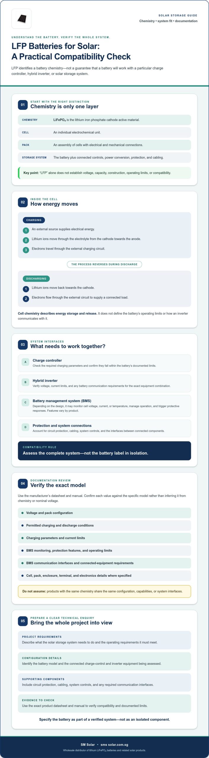
    An LFP battery is a lithium-ion battery that uses lithium iron phosphate (LiFePO4) as its cathode active material. This definition identifies the chemistry, not the full construction, rating or capabilities of a battery product. For solar project planning, that distinction matters: chemistry is one part of the specification, while cell design, pack configuration and system interfaces determine how the battery fits into the project.

    What does LFP mean in a battery?

    LFP stands for lithium iron phosphate. The formula LiFePO4 refers to the cathode material, one electrode component inside a cell. It doesn’t describe every material or electronic component in a finished battery. An LFP battery belongs to the broader lithium-ion family, whose members use different electrode chemistries while relying on lithium-ion movement during operation. For an overview of the chemistry and its applications, see Lithium iron phosphate (LFP) battery.

    Keep the terms precise in technical documents. Cathode means the positive electrode during discharge; cell means an individual electrochemical unit; pack means an assembly of cells with electrical and mechanical connections. A product described as “LFP” identifies its chemistry category, but the label alone doesn’t establish its voltage, capacity, construction or suitability for a particular application.

    LFP cell, battery pack, and storage system: what is the difference?

    A cell is the basic electrochemical unit. Multiple cells can be connected and assembled into a battery pack, which may also include an enclosure, terminals, monitoring or protection electronics, depending on its design. The exact arrangement varies by product. Confirm cell and pack details in the manufacturer’s documentation rather than assuming that all products using the same chemistry share a common configuration.

    A storage system is broader than the battery pack. In a solar application, it can include the battery alongside charge-control equipment, an inverter, circuit protection, cabling and system controls. Each component has its own specifications and interfaces. The project needs to account for the complete arrangement, not just the chemistry printed on the battery label.

    Terminology check: LiFePO4 identifies the cathode chemistry; “cell” identifies an electrochemical unit; “pack” identifies an assembly of cells; and “storage system” describes the battery together with connected control and power-conversion equipment.

    How an LFP Battery Stores and Delivers Electrical Energy

    Energy storage involves two linked processes: electrochemical reactions inside the cells and electrical control by the connected equipment. Understanding the distinction helps when assessing an lfp battery for a solar system. Chemistry describes how a cell stores and releases energy; it doesn’t specify the battery’s operating limits or how an inverter communicates with it.

    What happens during charging and discharging?

    During charging, an external source supplies electrical energy. Lithium ions move through the electrolyte from the lithium iron phosphate cathode towards the anode, while electrons travel through the external charging circuit. During discharge, the process reverses: lithium ions move back towards the cathode, and electrons flow through the external circuit to supply a connected load.

    These directions describe the cell-level process, not guaranteed product performance. The charging source and system controls must follow the battery manufacturer’s specified limits. Check the exact model’s documentation for permitted charging and discharge conditions, and don’t infer operating parameters from chemistry alone. The LFP and NMC chemistry overview from Pacific Northwest National Laboratory provides further context on lithium-ion chemistry.

    What does the battery management system do?

    Cell chemistry governs electrochemical energy storage; the battery management system (BMS) monitors and manages operation within product-defined limits. Depending on the battery design, a BMS may monitor cell voltage, current or temperature and may control charging or trigger protective responses. These functions vary by product, so confirm the included features in the specific datasheet and manual.

    The BMS can also provide an interface between the battery and other system components. Where communications are provided, verify the protocol, connection method and required settings against both the battery and inverter documentation. A shared connector or protocol name alone doesn’t establish compatibility. Confirm which data is exchanged, whether the inverter supports the battery’s communication method, and what operating behaviour applies if communication is unavailable.

    Cell activity doesn’t convert power for household or system loads. The battery supplies DC power; an inverter performs power conversion where AC output is required. Charge controllers and protection devices have separate roles and must be selected against the battery and project specifications. Use the manufacturer’s documented environmental and operating limits when assessing where and how the battery will be used. Avoid applying generic temperature assumptions to a specific model.

    For project enquiries, SM Solar’s wholesale solar product range includes lithium LiFePO4 batteries and related solar hardware. Include the battery model and relevant component datasheets so the required interfaces can be checked.

    LFP Battery Compatibility: Check System Interfaces Before Specification

    Compatibility rule: verify the complete system interface before selecting a battery. An LFP battery’s chemistry doesn’t establish whether it will work with an existing charge controller or hybrid inverter. The components must align on electrical operating limits, protection requirements and, where used, communications. Compare the project environment with the battery’s documented operating limits, too. Don’t substitute general assumptions for the exact model’s datasheet.

    Which solar hardware interfaces should be checked?

    Start with the battery and charge-controller documentation. Confirm that the controller’s battery profile and charging settings fall within the battery manufacturer’s specified limits. Then compare the battery’s electrical requirements with the hybrid inverter’s supported battery input and operating conditions. A similar nominal voltage or an LFP setting in a menu isn’t enough to confirm full compatibility.

    Review the battery and system documentation for DC circuit protection requirements, including the specified protective-device type and placement. For communications, confirm the supported protocol, wiring or connection method, settings and control functions on both sides. Don’t assume two components interoperate because they use the same connector or list the same protocol name. The LFP battery supplier guide provides further supplier and standards context.

    How can a compatibility table prevent specification errors?

    Record each requirement alongside its source document and verification status. Leave values blank until they’re confirmed against the relevant manufacturer documentation. Mark unresolved items for supplier or manufacturer confirmation rather than treating them as compatible by default.

    Component Required parameter or check Source document Verification status
    Battery Voltage, current, charging limits and environmental operating limits Exact battery datasheet and manual Confirm for selected model
    Charge controller Battery profile, adjustable charging settings and supported limits Controller datasheet and manual Compare with battery requirements
    Hybrid inverter Battery input range, charging capability and operating conditions Inverter datasheet and manual Confirm against both devices
    DC protection Protective-device requirements and installation arrangement Battery and system documentation Confirm for system design
    Communications Protocol, connection, settings and supported control functions Battery and inverter documentation Confirm end-to-end support

    Keep confirmed specifications separate from open questions. This creates a traceable basis for reviewing the system and clarifying unresolved interfaces before equipment selection.

    LFP Battery: Chemistry, System Integration and Selection Guide

    How to Review an LFP Battery Specification for a Solar System

    Review the battery against the project, not as a standalone product. A consistent process helps identify missing information before selection. Use manufacturer documentation for every limit and value. Don’t fill gaps with industry averages or assumptions based on chemistry.

    Which battery datasheet fields should a technical reviewer record?

    Use the exact model’s datasheet and manual. Record specifications as published, including units, conditions and qualifications. Capture the battery’s electrical ratings and limits, stated environmental operating conditions, protection features and communication interfaces. Also note the document title and revision so reviewers can trace each value to its source.

    If a field is absent, unclear or inconsistent with another document, mark it as unresolved. Request written confirmation from the manufacturer or supplier before treating it as a design input. A blank field is safer than an assumed value.

    How should the battery be integrated into a solar design?

    Map the battery alongside the charge controller, hybrid inverter and DC circuit protection devices. Check wiring, control functions and operating requirements against the approved project documents and the documentation for each selected component. Installation and commissioning decisions should be handled by qualified project personnel using applicable documentation.

    Use this review sequence:

    • 1. Define the project. Record the required system function, load profile, solar-system configuration and integration constraints from the project documents.
    • 2. Review the battery. Capture the exact model’s electrical, environmental, protection and communications specifications, preserving stated units and conditions.
    • 3. Cross-check connected equipment. Compare the battery requirements with the charge-controller and inverter documentation, then check DC protection requirements against the battery and system design.
    • 4. Map interfaces. Document wiring and control connections, including any communication method or supported control function that the design depends on.
    • 5. Resolve open items. Flag missing, conflicting or unclear values for written confirmation. Keep confirmed specifications separate from pending checks.

    Include the project’s expected environmental conditions in the review, then compare them with the exact battery documentation. Don’t infer temperature limits or operating suitability from the LFP label. The same rule applies to voltage, current, charging and protection values.

    Use this record as the basis for a complete technical enquiry. Send SM Solar your battery and related component requirements for a wholesale product enquiry.

    Sourcing LFP Batteries and Coordinating Solar System Components

    A useful supplier enquiry connects the battery request to the project’s full equipment configuration. Include the intended system function, documented electrical requirements and relevant project constraints. This gives the supplier context to respond to the specification rather than to the chemistry label alone.

    What information should an LFP battery supplier enquiry include?

    Prepare a concise enquiry package with the information needed to assess product fit and system interfaces:

    • Project requirements: intended system function, load profile, configuration and relevant environmental or installation constraints documented for the project.
    • Electrical requirements: required values and operating conditions drawn from the project design, with units and source documents retained.
    • Connected equipment: the selected charge controller, hybrid inverter and DC circuit protection hardware, including model details where available.
    • Interface details: wiring, communications and control requirements that need confirmation across the battery and other components.
    • Open questions: any missing, unclear or conflicting specifications, with a request for current product documentation and written confirmation.

    Attach relevant datasheets or identify their document revisions. Separate confirmed design inputs from items awaiting confirmation. Don’t use assumed values to complete the request; that can conceal a compatibility issue until later in procurement or system review.

    How does SM Solar fit into a solar hardware supply workflow?

    SM Solar is a wholesale distributor of solar products, including lithium LiFePO4 batteries. Its related solar hardware categories include charge controllers, hybrid inverters and circuit protection, alongside solar panels and other DC-related products. Coordinating the enquiry around the battery and its supporting components can help clarify which specifications and interfaces need to be reviewed together. Confirm product models and specifications directly for each enquiry.

    The company profile also states system integration, installation and after-sales maintenance capabilities for end users. Refer to the profile for the scope of those capabilities, and don’t assume they apply to every project or enquiry. For additional supplier and standards context, consult the LFP battery supplier guide.

    For a technical product enquiry, provide your project requirements, selected component details and unresolved specification questions to SM Solar. This gives the wholesale distributor a clear basis for discussing lithium LiFePO4 batteries and related solar hardware without presuming a particular model or availability.

    Specify the Battery as Part of the Complete Solar System

    An lfp battery specification is only a starting point. The chemistry identifies the battery category, while product documentation defines its operating limits, protection functions and communication interfaces. Review those details alongside the charge controller, hybrid inverter and circuit protection requirements before confirming system compatibility.

    Keep project requirements, component details and open questions together in a clear technical record. Use exact-model datasheets, preserve units and conditions, and request confirmation for missing or conflicting values rather than relying on assumptions. This makes supplier discussions more focused and supports a better-informed selection.

    SM Solar distributes lithium LiFePO4 batteries and other solar products on a wholesale basis. Its company profile also states system integration and after-sales maintenance capabilities. To share your project requirements and related hardware details, submit your LFP battery and solar hardware requirements.

    A documented, system-level review gives your project a clearer basis for the next specification decision.

    Frequently Asked Questions

    What is an LFP battery?

    An LFP battery is a lithium-ion battery that uses lithium iron phosphate, with the chemical formula LiFePO4, as its cathode material. LFP names the cell chemistry, not every component in the finished battery or storage system. The complete product may include assembled cells, terminals, an enclosure and battery-management electronics. Check the exact model’s documentation for its construction, ratings and operating limits.

    Is an LFP battery the same as a LiFePO4 battery?

    Yes. LFP is the common abbreviation for lithium iron phosphate, and LiFePO4 is its chemical formula. The names refer to the same cathode chemistry. They don’t mean that every battery using this chemistry has an identical cell arrangement, capacity, control features or electrical specifications. For procurement, confirm the exact model and review its datasheet rather than relying on either label alone.

    How does an LFP battery work?

    An LFP battery stores and releases energy through controlled electrochemical reactions. During charging, lithium ions move through the cell from cathode towards anode, while electrons flow through the external charging circuit. During discharge, the movement reverses and electrons travel through the connected circuit to supply a load. The battery’s operating conditions depend on the manufacturer’s documentation, not on a generic description of the chemistry.

    Can an LFP battery work with any solar inverter?

    No. Compatibility depends on the battery’s documented electrical limits and the inverter’s supported battery input, charging settings and operating requirements. If the battery relies on communications with the inverter, confirm that both devices support the relevant protocol, connections and control functions. Check the battery and inverter datasheets together. Similar nominal voltage or a selectable LFP setting alone doesn’t prove that the equipment is compatible.

    What does a battery management system do in an LFP battery?

    A battery management system (BMS) monitors and manages battery operation within limits defined for the product. Depending on the design, it may monitor cell voltage, current or temperature and provide protective responses or communications. Features vary, so confirm them in the exact battery’s datasheet and manual. If the inverter uses BMS data, verify communication requirements and supported controls in both manufacturers’ documents.

    What should I check on an LFP battery datasheet?

    Check the exact model’s voltage, capacity, current ratings, charging and discharge limits, environmental operating conditions, protection features and communication interfaces. Preserve the units, conditions and qualifications stated by the manufacturer. Compare relevant values with the charge controller, inverter and circuit protection documentation. Flag missing, unclear or conflicting information for written confirmation. Don’t fill gaps with typical values from another model or general industry guidance.

    Can an LFP battery be used in an off-grid solar system?

    Yes, an LFP battery can be considered for an off-grid solar system if its documented specifications suit the project and the connected equipment is compatible. Define the system function and load profile, then review the battery alongside the charge controller, inverter and circuit protection. Confirm wiring, control interfaces and environmental limits against product and project documentation. A chemistry label alone can’t confirm suitability for a specific design.