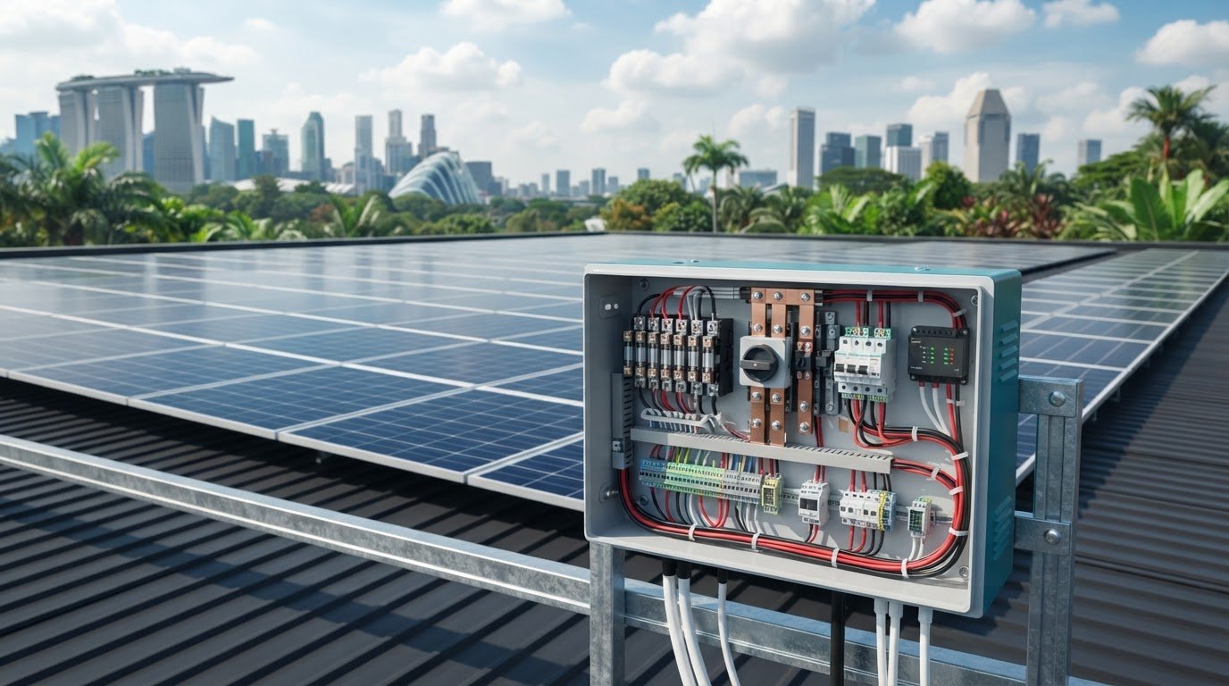
A solar combiner box is defined not just by its parts list, but by how its components work together. Solar combiner box components can include string fuses, busbars, a DC disconnect, surge protection, terminals and monitoring devices. The right arrangement depends on the PV system design. Selecting components individually without checking their ratings and interfaces can create compatibility gaps between the array, combiner box, inverter and system wiring.
To specify a box effectively, first identify which circuits it needs to combine and where its output will go. Then check which connection, protection and isolation functions belong in the assembly. This guide explains the role of common components, how array configuration influences selection, and what to review when specifying equipment for a project in Singapore.
Use the practical checks below to coordinate component ratings and connections with string count, system voltage, inverter inputs and wiring. For projects that need coordinated DC hardware, SM Solar supplies solar components and provides system integration and installation for end users.
Key Takeaways
- Identify the main solar combiner box components and distinguish connection parts from protection and isolation devices.
- Use string count and array layout to define the box configuration, then assess device ratings against the system design.
- Review system documentation, component compatibility, enclosure, terminals and supporting documents before procurement.
- Coordinate the combiner box with inverter inputs and PV wiring to reduce mismatches across the DC system.
- SM Solar’s wholesale supply and system integration capabilities support coordinated sourcing for on-grid and off-grid projects.
What Is a Solar Combiner Box, and Where Does It Fit in a PV System?
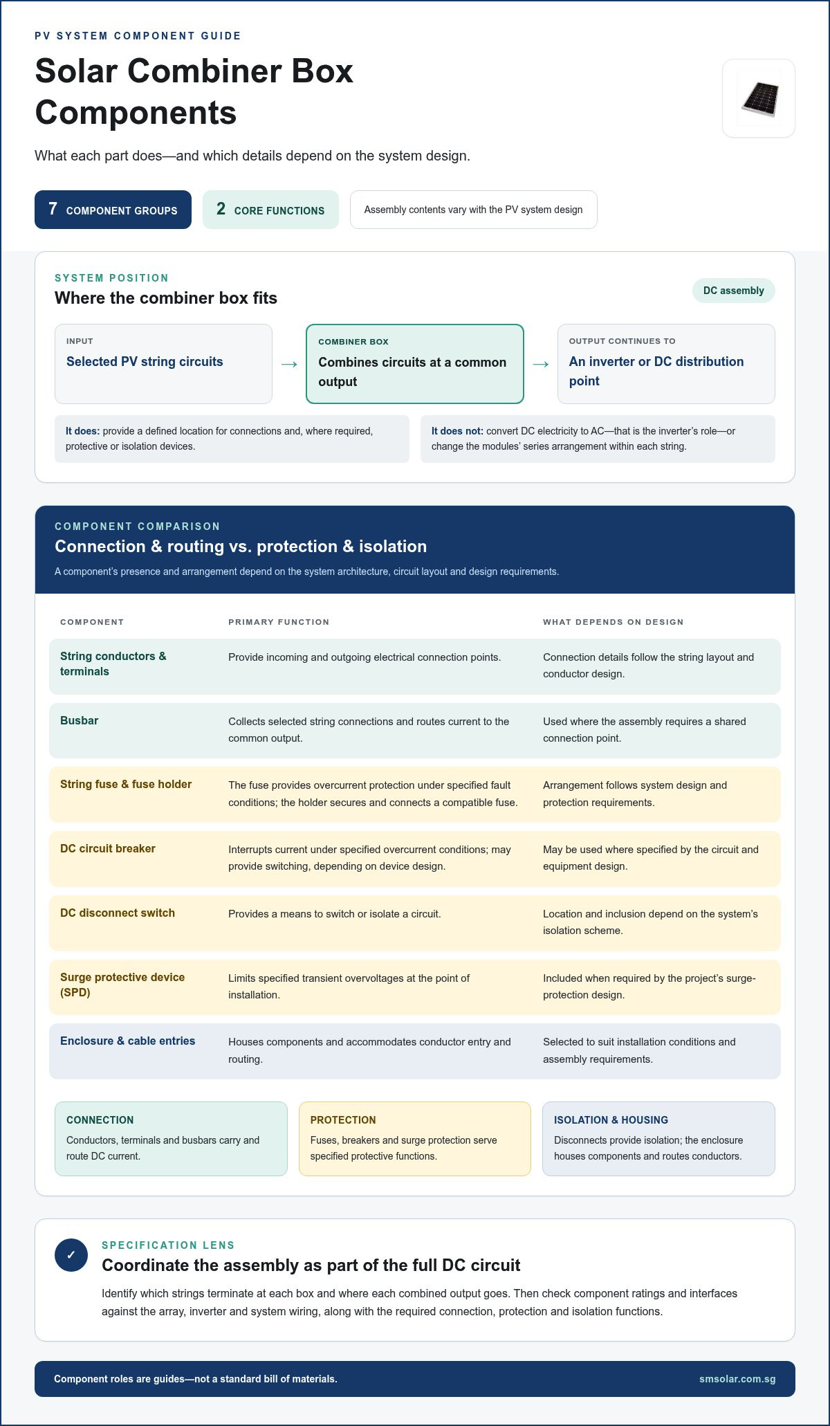
A solar combiner box is a DC assembly that brings selected photovoltaic (PV) string circuits together at a common output. It sits between the PV array and downstream equipment, such as an inverter or a DC distribution point. Consolidating string outputs can reduce the number of separate circuit runs continuing from the array. The box also provides a defined location for connections and, where the design requires them, protective or isolation devices.
A combiner box does not convert the array’s DC electricity into AC. That is the inverter’s role. Nor is it an AC distribution board, which distributes power on the AC side of a system. A fuse, disconnect or surge protective device has a specific circuit function; a combiner box is an assembly that may house selected devices alongside the connections. Its contents depend on the system architecture, circuit layout and design requirements.
How does a combiner box connect PV strings?
PV modules connected in series form a string, which creates an individual DC circuit from the array. The string conductors are routed to the combiner box and connected at designated points. The box brings selected circuits to a common output that continues toward downstream equipment. It consolidates the circuits but does not change the modules’ series arrangement within each string.
Array topology determines whether a system uses one box, multiple boxes or another routing arrangement. For example, strings in separate array sections may go to different boxes before their outputs connect farther downstream. The design should show which strings terminate at each box and where each output goes. This circuit-level view helps distinguish the number of array strings from the number of combiner boxes required.
Which systems use a solar combiner box?
A combiner box is commonly used when a PV design has multiple string circuits to consolidate before they connect to downstream equipment. It can organise array wiring and provide a location for protection and isolation devices specified by the design. A system with fewer strings, or with an inverter and wiring arrangement designed to accept separate string inputs, may use a different layout. The equipment interfaces and project documents determine the suitable arrangement.
Assess the box as part of the full DC circuit, not as a standalone enclosure. Review the array layout, inverter input arrangement, cable routing and protection strategy together. The solar circuit protection devices guide provides further context on protective devices in PV systems. Combining circuits may simplify connections, but it does not replace the need to select and coordinate suitable protection across the system.
Before specifying the assembly, use the system diagram to identify which strings enter each box and where each combined output goes. Then determine which connection, protection and isolation functions the architecture requires. This establishes the box’s role in the PV system and provides a basis for reviewing its components.
Solar Combiner Box Components and the Function of Each Part
Solar combiner box components serve two broad purposes: carrying and routing DC current, or providing protection and isolation. The assembly varies with the system. One design may use string fuses, a disconnect and surge protection, while another may place some of those functions elsewhere. Treat the list below as a guide to component roles, not a standard bill of materials.
| Component | Primary function | Configuration-dependent status |
|---|---|---|
| String conductors and terminals | Provide the incoming and outgoing electrical connection points. | Required connection details depend on string layout and conductor design. |
| Busbar | Collects selected string connections and routes current to the common output. | Used where the assembly design requires a shared connection point. |
| String fuse and fuse holder | Fuse provides overcurrent protection under specified fault conditions; holder secures and connects the compatible fuse. | Required arrangement depends on system design and protection requirements. |
| DC circuit breaker | Interrupts current under specified overcurrent conditions and may provide switching, depending on device design. | May be used where specified by the circuit and equipment design. |
| DC disconnect switch | Provides a means to switch or isolate a circuit. | Location and inclusion depend on the system’s isolation scheme. |
| Surge protective device (SPD) | Limits specified transient overvoltages at the point of installation. | Included when required by the project’s surge-protection design. |
| Enclosure and cable entries | Houses components and accommodates conductor entry and routing. | Selected to suit installation conditions and assembly requirements. |
String fuses, fuse holders and busbars
A string fuse is designed to protect its circuit against specified overcurrent conditions. Select it based on the PV circuit and equipment design, and confirm that it is compatible with its holder and suitable for the DC application. The holder provides the mechanical mounting and electrical interface. A busbar brings selected circuits together and carries the combined connection toward the box output. Check that the terminal arrangement and conductor capacity match the design documents.
String protection limits fault current in a circuit. Circuit isolation provides a means to disconnect one part of the system from another. These functions are related but not interchangeable.
DC circuit breakers, disconnects and surge protection
A DC circuit breaker provides overcurrent protection, while a disconnect switch is intended to open or isolate a circuit. A breaker may also provide switching, but its protective function and rating must suit the application. Select devices using their documentation and the project design, not appearance alone. The DC circuit breakers for solar guide explains key selection considerations.
An SPD addresses specified transient overvoltages; it does not replace overcurrent protection or circuit isolation. Its placement and coordination should follow the project design. For broader solar technology context, see the U.S. Department of Energy Solar Energy Technologies Office. For solar circuit protection and related DC hardware, explore SM Solar’s solar product range.
How PV Design Changes Solar Combiner Box Component Selection
Start combiner-box planning with the array and downstream equipment, not a standard parts list. String count and physical layout help determine how circuits are grouped and routed. They do not, on their own, set fuse, disconnect, conductor or busbar ratings. Those decisions require system design data, including circuit voltage, operating and fault current, and the inverter’s input limits.
| Design factor | Effect on connection planning | Effect on component selection |
|---|---|---|
| String count | Determines the incoming circuit connections and how they may be grouped. | Informs the required number of connection points; it does not alone determine device ratings. |
| Array topology and location | Influences where circuits can be consolidated and how output cables route toward downstream equipment. | Affects enclosure arrangement, terminal layout and cable-entry planning. |
| System voltage | Defines the electrical conditions across connected DC circuits. | All relevant devices and insulation arrangements must suit the designed voltage. |
| Operating and fault current | Informs the expected current in each circuit and the combined output. | Guides selection and coordination of conductors, busbars and protection devices. |
| Inverter or controller interface | Sets the destination and input arrangement for the combined circuits. | Requires checking the equipment’s documented limits and connection requirements. |
String count, array topology and combining points
Before choosing where circuits should combine, map each string to its array section, planned cable route and destination. If strings are spread across separate roof areas, for example, the design may route them to different combining points to suit cable paths or equipment interfaces. That does not prescribe a fixed number of boxes. Use the single-line diagram and site layout to establish the arrangement.
Keep connection planning separate from rating decisions. A layout drawing can show how many circuits reach a box and where its output goes. Electrical calculations and equipment documentation establish the conditions each component must handle. Component ratings must match the designed circuit.
Protection requirements and inverter interfaces
Compare the inverter’s documented DC input voltage range, allowable current and input configuration with the array and proposed combiner output. Circuits can fit the terminals and still be incompatible with the inverter. For a system using a charge controller, review its PV input requirements against the array and downstream battery architecture. Include relevant fault conditions when assessing protective devices and conductor coordination.
Protection coordination depends on the complete circuit design, including the PV source, conductors, protective devices and receiving equipment. Do not select a fuse or breaker based on string count alone. Check device ratings and coordination against project documents and the electrical requirements applicable to the installation in Singapore. The National Electrical Code (NFPA 70) is a U.S. code reference, not a substitute for confirming requirements that apply to a Singapore project.
How to Specify and Review a Solar Combiner Box
Use a traceable review process: start with approved system documents, turn their requirements into a component specification, then compare the supplied assembly with the approved design before installation and commissioning. Keep design verification separate from physical inspection. A box can look complete while containing a device or connection arrangement that does not match the project.
What information belongs in the specification?
Build the specification from the array schedule, single-line diagram, circuit calculations and inverter documentation. Record the string arrangement, circuit voltage and current data, expected fault conditions, output destination, cable routes and installation environment. These details provide the basis for selecting solar combiner box components without assuming a standard configuration.
Use approved design documents to identify protective-device characteristics, isolation requirements and coordination. Specify enclosure conditions, cable-entry positions, terminal types, conductor ranges and labelling needs as required for the project. Check the codes and standards that apply to the Singapore project rather than importing requirements from another market.
Use this review sequence:
- Establish the design basis. Confirm the current approved drawings, array schedule, circuit data and equipment documentation.
- Translate requirements. Record the required string connections, output arrangement, protection and isolation functions, environmental conditions and interface limits.
- Compare selections. Match proposed device ratings and connection details to the design calculations and receiving equipment requirements.
- Review the assembly. Check the enclosure, terminals, entries, labels and component identification against the specification.
- Record discrepancies. Resolve differences through the project’s document-control and approval process before installation proceeds.
What should be checked before commissioning?
Physical inspection verifies the delivered and installed assembly, but does not replace design approval. Compare the component schedule and approved drawings with the actual devices. Check for visible damage, correct wiring identification, secure and correctly located conductors, clear labels, suitable cable entries and proper enclosure closure. Confirm that the assembly’s location and connections align with the project drawings.
Follow the applicable project procedures and equipment documentation for commissioning tests, methods and acceptance criteria. Record inspection findings and approved changes so the final installation remains traceable to its design. A visual check alone does not verify electrical performance or protection coordination.
Specification checklist
- System voltage, circuit current and fault-condition data correspond to approved design documents.
- Protective and isolation devices suit their assigned circuits and the inverter or controller interface.
- Enclosure, cable entries, terminals, conductor ranges and labelling meet project requirements.
- Device markings, drawings and technical documents match the supplied assembly.
- Applicable jurisdictional requirements and project acceptance procedures are identified.
For coordinated sourcing of solar circuit protection and related DC hardware, explore SM Solar’s solar products.
Sourcing and Integrating Combiner Box Components with SM Solar
Combiner-box selection connects several parts of a PV system. Fuses, disconnects, surge protection, conductors and terminals must suit the circuit design and work with downstream equipment. Coordinated sourcing lets project teams review these relationships together instead of treating each DC component as a separate purchase. Use the specification as the basis for selection, and compare component ratings, interfaces and documentation with the approved design before procurement and installation.
This coordination applies to both on-grid and off-grid systems. A combiner-box output may connect to an inverter or, in a system that uses one, a solar charge controller. The interface affects the protection and connection arrangements required across the wider DC system. Reviewing related equipment documentation together can help identify mismatches in ratings, connection points or intended functions before assembly.
Coordinate protection hardware with the wider DC system
Review the protection strategy across the full DC path, from array circuits through the combiner assembly to the receiving equipment. Each protective device must suit its circuit and function, and the inverter or controller interface shapes the connection plan. For an overview of how protective devices fit into PV design, consult the solar circuit protection devices guide.
If the system uses a solar charge controller, compare its input requirements with the array design and related DC equipment. The MPPT solar charge controller specifications guide can support that review. Keep device ratings, protection coordination and connection details tied to project documents. A general product category alone does not establish compatibility.
SM Solar’s supply and project support
SM Solar is a wholesale distributor of solar products, including solar circuit protection and other DC-related hardware. Its product range also includes solar panels, charge controllers and hybrid inverters. SM Solar provides system integration, installation and after-sales maintenance for end users, supporting projects that need product supply alongside these capabilities.
Before comparing components, document the array configuration, circuit data, receiving equipment, environmental conditions and required protection functions. Then assess products against the approved specification and record any design differences for review. This gives the project team a clear basis for sourcing without assuming every system needs the same combiner-box arrangement or component set.
Explore SM Solar’s solar products to review equipment for your PV system requirements.
Move from Specification to a Coordinated PV Design
Use approved system documents to connect design decisions with procurement. Before placing orders, turn the combiner-box schedule into a clear component and connection record, then align it with the array layout, downstream equipment interfaces and installation drawings. This gives the project team a shared reference for managing design changes and maintaining traceability through assembly and commissioning.
Apply the same approach when reviewing solar combiner box components alongside other DC hardware. Record approved substitutions or revisions, and ensure updated documents reach the people responsible for procurement, integration and installation. For engineering teams managing broader bills of materials or sourcing discrete electronic parts for power systems, Adage Components provides dedicated component distribution and BOM support. A consistent record keeps decisions visible as the project moves from specification to site work.
For your next PV project, let the system design guide sourcing and coordination. Explore SM Solar’s solar products to plan the equipment required for your application.
Frequently Asked Questions
What components are commonly found in a solar combiner box?
Common solar combiner box components include string terminals, busbars and an enclosure. Fuses and other protective devices are included when the design calls for them. Some assemblies also include a disconnect, surge protection or monitoring. For example, a project may specify current monitoring to compare string performance. The equipment schedule and circuit diagram show which functions belong in the box and which are provided elsewhere in the PV system.
Are string fuses required in every solar combiner box?
No. String fuses are not automatically required in every box. Their use depends on the array configuration, possible fault-current paths and the system’s documented protection strategy. A designer may assess whether parallel-connected strings could expose a circuit to current from other strings during a fault. Use the approved electrical design and equipment instructions to determine whether fuses are needed and which characteristics suit the application.
What is the difference between a combiner box and a DC disconnect?
A combiner box is an assembly that may bring several PV circuits together and house selected devices. A DC disconnect is a switching device intended to open or isolate a DC circuit. Depending on the design, a disconnect may be installed inside a combiner enclosure or elsewhere in the system. Do not assume that a combiner box provides isolation unless the specified assembly includes a suitable disconnect function.
Does every solar system need a combiner box?
No. A combiner box is useful when the design calls for multiple PV string circuits to be consolidated, but another arrangement may suit systems with fewer strings or equipment that accepts separate string inputs. For example, an inverter with suitable independent inputs may receive array circuits without a separate combining enclosure. The single-line diagram and equipment connection requirements determine whether a box is needed.
Where is a solar combiner box installed?
A combiner box is installed on the DC side of the system, where it suits the array wiring and route to the receiving equipment. Its location depends on cable routes, access for inspection and maintenance, mounting conditions and the approved layout. For outdoor installations, the design should account for exposure to rain, moisture, heat and other site conditions while maintaining safe access and suitable cable entry arrangements.
Can a charge controller connect to a solar combiner box?
Yes, if the system routes combined PV circuits to a charge controller and the controller’s PV input supports the resulting electrical conditions. Check its input limits, polarity, connection arrangement and required protective devices against the controller documentation and system design. A combiner box does not replace the controller or determine battery-side wiring. Keep the PV input path distinct from the controller’s battery connections.
What enclosure rating should a solar combiner box have?
No single enclosure rating suits every installation. Select an enclosure based on exposure, mounting position, moisture and dust risks, temperature conditions and any corrosive agents at the site. For outdoor projects in Singapore, account for weather exposure in the design. Compare the enclosure’s documented protection rating with project requirements, installation conditions and applicable local requirements rather than choosing by appearance alone.