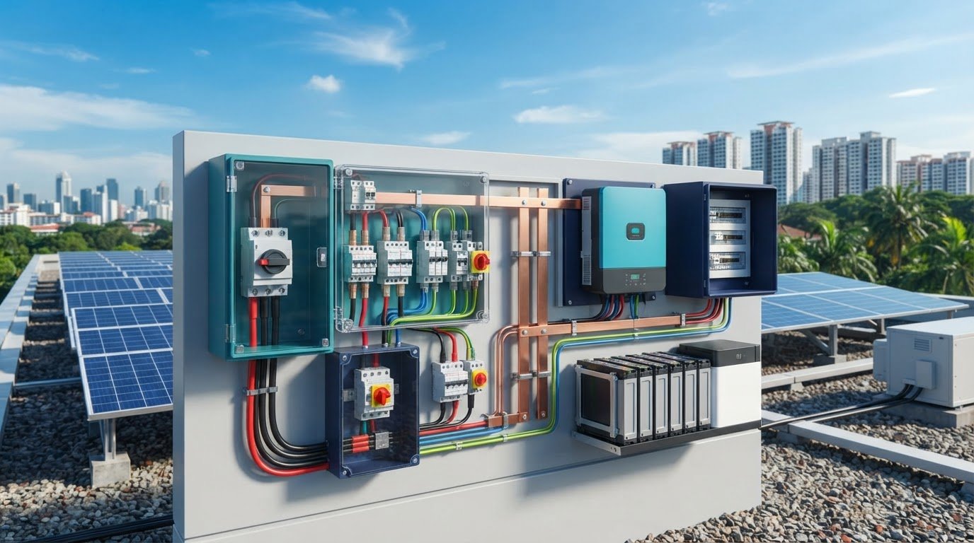
What if a protection device selected for one part of a PV system leaves another circuit exposed? Solar circuit protection devices serve different functions, and similar catalogue names can hide important differences. A PV string, battery circuit and power-conversion stage each have distinct protection requirements.
Choosing devices by product label alone isn’t enough. Effective protection depends on how components work together along the system’s power path, from the array through storage and conversion equipment. Selection also needs to reflect the project design and applicable requirements in Singapore.
This guide explains the main protection-device categories used in PV systems and the role each plays in a typical setup. It covers how to assess suitability by circuit and fault condition, then provides a practical checklist for technical review and procurement. The aim is coordinated protection, not simply a longer equipment list.
Key Takeaways
- Understand how solar circuit protection devices fit across the PV array, conversion equipment, storage and connected loads.
- Distinguish overcurrent protection from isolation, switching and transient-voltage protection when comparing fuses, DC breakers, disconnects and SPDs.
- Evaluate each circuit according to its type, operating conditions, equipment limits and fault-current considerations instead of relying on one device for the whole system.
- Use a structured review of circuit diagrams, device schedules and documentation to support technical review and procurement.
- See how circuit protection fits within a broader solar hardware supply and system integration approach.
Solar circuit protection devices: what they protect in a PV system
Solar circuit protection devices are selected to protect, isolate or manage specified electrical conditions. They aren’t interchangeable: a device suitable for a PV array circuit may not be suitable for a battery circuit or an inverter connection. The protection design follows the system’s electrical architecture, equipment limits and applicable requirements in Singapore.
Where protection devices fit along the solar power path
A typical system moves energy from PV modules through DC-side equipment to an inverter, then to storage, distribution circuits or connected loads. The arrangement varies by system. Not every installation has a battery, and equipment order can differ.
Representative power path: PV modules → PV-side protection and isolation → charge controller or inverter → battery-side protection, where storage is used → AC or DC distribution → connected loads
Protection is placed on relevant circuits, such as PV string or array conductors, battery connections, inverter inputs or outputs, and distribution circuits. Overcurrent protection limits specified fault effects on conductors and equipment. Isolation and disconnecting devices serve a different purpose: they separate circuits for maintenance or shutdown. A disconnect alone doesn’t necessarily provide overcurrent protection, and opening one circuit doesn’t isolate every energy source in the system.
What electrical faults and transients require consideration
Overcurrent is current above the intended operating level, which can result from an overload or fault. A short circuit is an unintended low-impedance path between conductors or to ground. It can produce fault current that stresses wiring and connected equipment. Protection selection must account for the circuit’s operating conditions and the limits of the equipment it serves.
Transient overvoltage is a brief voltage rise, such as one associated with lightning effects or switching. It differs from sustained overcurrent: an overcurrent device responds to excessive current, while a surge protective device is intended to limit transient voltage on its designated circuit. Inverters also have operating and grid-interface functions. For example, anti-islanding protection addresses continued inverter operation when grid supply is interrupted, rather than replacing circuit protection.
Protection must match the circuit’s voltage, current, fault conditions and equipment limits. A device selected for one part of a PV system cannot be assumed to protect every other part. Map each energy source and circuit to its protection and isolation functions, then check the choices against applicable project requirements.
How solar fuses, DC breakers, disconnects, and SPDs differ
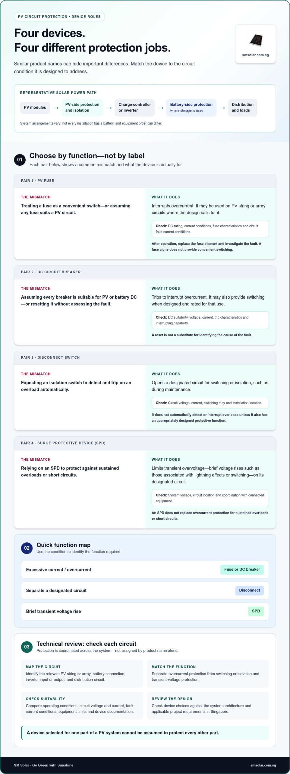
These devices address different electrical conditions. Fuses and circuit breakers provide overcurrent protection; disconnect switches provide switching or isolation; surge protective devices (SPDs) limit transient overvoltage. Some equipment can combine functions, but don’t infer a device’s function from its product label alone.
Overcurrent protection: fuses and DC breakers
A fuse interrupts excessive current when its element melts. After it operates, the fuse element must be replaced, and the cause of the fault should be investigated. A circuit breaker trips through its operating mechanism and can generally be reset after the fault is assessed. Neither type is automatically suitable for every PV or battery circuit. Confirm DC suitability, voltage rating and interrupting capability against the circuit’s prospective fault current and the device documentation.
| Device | Function and typical role | Selection inputs | Key limitation |
|---|---|---|---|
| PV fuse | Interrupts overcurrent; may be used on PV string or array circuits where the design calls for it. | DC rating, current conditions, fuse characteristics and circuit fault-current conditions. | Operated elements require replacement; a fuse does not provide a convenient switching function by itself. |
| DC circuit breaker | Trips to interrupt overcurrent; may also provide switching where designed and rated for that use. | DC suitability, voltage, current, trip characteristics and interrupting capability. | Resetting is not a substitute for identifying the fault; not every breaker is suitable for PV or battery DC. |
| Disconnect switch | Opens a designated circuit for isolation or switching, such as for maintenance. | Circuit voltage, current, switching duty and installation location. | Doesn’t automatically detect or interrupt overloads unless it also has an appropriately designed protective function. |
| SPD | Limits transient overvoltage on the circuit it is intended to protect. | System voltage, circuit location and coordination with connected equipment. | Doesn’t replace overcurrent protection for sustained overloads or short circuits. |
Switching, isolation and transient protection
A disconnect opens a designated section; it isn’t necessarily a protective device that trips automatically. An SPD responds to brief voltage surges, not sustained excessive current. For technical background on transient surges and how suppression units mitigate them, resources from Energy Control Systems outline the fundamentals of transient voltage protection. These distinctions matter across PV, battery and inverter circuits, where operating conditions and equipment limits differ. The PV system safety guidance discusses protection considerations such as overcurrent and reverse current.
Fuses and breakers address overcurrent, disconnects provide isolation, and SPDs limit transient overvoltage. Final selection and coordination must follow device documentation, circuit design and applicable project requirements in Singapore. For project planning, solar circuit protection products can be considered alongside the wider solar hardware schedule.
How to evaluate solar circuit protection for each circuit
A single fuse or breaker cannot be assumed to protect an entire PV system. The array, battery, inverter connections and distribution circuits have different sources, operating conditions and equipment limits. Evaluate each circuit separately, then review how its protective devices coordinate with connected equipment and with one another.
Selection inputs for PV array and battery circuits
Start with the circuit diagram and equipment documentation. For each circuit, identify its function, conductors, connected equipment and possible fault-current paths. Compare expected voltage and current conditions with the limits of the conductors, equipment and proposed protective device. Don’t select a device based on nominal system voltage alone.
Review PV array and battery circuits separately. Array conditions depend on the PV configuration and operating characteristics of the modules. Battery-side assessment must account for the battery and connected equipment, including fault conditions specified in their documentation. A device appropriate for an array circuit may not have the required characteristics for a battery connection.
- PV array: Review configuration, expected operating conditions, conductor protection needs and connected equipment instructions.
- Battery: Assess battery documentation, circuit conductors, connected equipment limits and available fault-current conditions.
- Both: Confirm that the protective device is intended for the circuit’s DC application and has suitable ratings and interrupting capability.
Detailed calculations should follow the system design and be reviewed by a qualified electrical designer. Avoid default ratings or universal sizing rules: the correct values depend on the actual circuit and applicable project requirements.
Coordination, compatibility and installation environment
Protection should address the intended fault while respecting the limits of connected equipment. Review device characteristics against the circuit design, including how protective devices at different points interact. A device’s current rating alone doesn’t establish that its response or interrupting capability is appropriate.
Check product documentation for connection method, polarity, enclosure requirements and permitted installation conditions. Confirm that the device is installed in the intended position and that its terminals and enclosure suit the project environment. Resolve these compatibility details before procurement instead of inferring them from a catalogue description.
For projects in Singapore, verify current applicable requirements and standards for the specific system and installation. Record the design basis, selected device details and supporting calculations for technical review. This makes it easier to assess whether each device matches its circuit, rather than treating a broad list of solar circuit protection devices as a complete protection design.
How to review a PV protection layout before procurement
Begin procurement review with the approved circuit design, not a catalogue. Trace each circuit on the diagram, identify its protection and isolation functions, then compare the proposed components with equipment documentation. This helps expose missing details before they become assumptions in a bill of materials.
Build a circuit-by-circuit protection schedule
Create a schedule that links each circuit to its protective device, connected equipment and design reference. Include PV array, battery, inverter and distribution circuits where they apply. Record each device’s intended function, such as overcurrent protection, isolation or transient-voltage protection, so similar product descriptions don’t obscure different roles.
- Circuit assignment: Identify the circuit and its connection points on the diagram.
- Device function: State the fault or operating condition addressed, and whether the device provides protection, switching or isolation.
- Compatibility: Compare device ratings and characteristics with the approved design and the connected equipment’s limits.
- Traceability: Record the device documentation and design references used for selection.
- Open items: Flag missing ratings, unclear interfaces or unresolved calculations for technical review. Don’t fill gaps with assumed standard values.
Use the schedule to reconcile the circuit diagram with the proposed equipment list. For a closer look at array distribution hardware, see Solar Combiner Box Components: Wiring and Protection. Review battery-side selections against battery and inverter documentation; the related Lithium LiFePO4 Battery Supplier Guide: Industrial Energy Storage Standards 2026 provides additional battery context.
Check integration, documentation and project requirements
Cross-check selected devices against relevant inverter, charge-controller and battery instructions. Confirm that circuit interfaces, installation conditions and protective functions align across the documents. A component that appears suitable on its own may not match the system configuration or another connected device’s limits.
Keep technical design approval distinct from product sourcing and installation planning. Design review establishes the functions and characteristics the project requires. Procurement matches those requirements to documented components, while installation planning addresses placement, connections and enclosure arrangements. Return any mismatch to design review before finalising the schedule.
For a Singapore project, verify current applicable requirements and standards through authoritative sources before making compliance decisions. Keep the reviewed diagram, device schedule, product documentation and outstanding design decisions together. This allows each selected solar circuit protection device to be traced to its circuit and design basis.
Include SM Solar’s solar circuit protection supply in the project’s broader solar hardware procurement planning.
Solar circuit protection supply and system integration with SM Solar
Circuit protection is one part of a complete solar hardware bill of materials. Its selection connects directly to the modules, charge controllers, batteries, inverter interfaces and distribution equipment in the project. Treating protection as an isolated purchase can leave component interfaces out of the review. A system-level view keeps circuit requirements connected to the equipment they serve.
Match protection hardware to the wider solar system
Start with the project architecture. PV modules establish the array circuits, while charge controllers and inverters define key conversion interfaces. Where storage is included, the battery circuit has its own equipment and protection requirements. Each connection in the power path should align with the approved design and documentation for the associated equipment.
SM Solar’s solar product categories include monocrystalline solar panels, solar charge controllers, lithium LiFePO4 batteries, hybrid inverters and solar circuit protection. For PV module context, refer to Monocrystalline Solar Panels Singapore: Technical Overview 2026. Planning these categories together supports a clearer review of interfaces and procurement requirements without treating any individual component as a complete system solution.
SM Solar is a wholesale distributor of solar products, including circuit protection devices and other DC-related products, with a core focus on 12 V DC solar products. The business has supplied solar-industry products since 2008. Its capabilities also include system integration, installation and after-sales maintenance for end users.
Move from technical review to project sourcing
Use the reviewed circuit diagram, protection schedule and approved device specifications as the basis for sourcing. The schedule should identify each circuit, required device function and relevant equipment interface. Compare product documentation with those requirements before adding components to the project bill of materials. This keeps technical approval distinct from procurement and installation planning.
For off-grid and on-grid projects, the wider system configuration affects which hardware categories need to be coordinated. Consider protection alongside the PV, conversion and storage equipment, and retain the design references used for each selection. This creates a traceable basis for integrating components into the project rather than ordering by category name alone.
For project sourcing, explore SM Solar’s solar products, including solar circuit protection and related DC hardware.
Turn the protection review into a project-ready plan
Effective PV protection depends on matching each device to its circuit and intended function. Fuses and DC breakers address overcurrent, disconnects provide switching or isolation, and surge protective devices respond to transient overvoltage. Don’t assume that one device protects every part of a system.
Before procurement, map requirements circuit by circuit and compare proposed devices with the approved design, equipment limits and product documentation. Keep unresolved ratings or compatibility questions within technical review, and verify applicable Singapore requirements for the project.
SM Solar is a wholesale distributor of solar products, including solar circuit protection devices and other DC-related products. Its capabilities include system integration, installation and after-sales maintenance. Use the reviewed circuit schedule and specifications as the basis for sourcing relevant hardware.
Explore SM Solar’s solar products and build your next procurement plan around clear circuit requirements and compatible components.
Frequently Asked Questions
What are solar circuit protection devices?
Solar circuit protection devices are electrical components designed to address specified fault conditions in a PV system. Examples include fuses or circuit breakers for overcurrent, disconnect switches for isolation, and surge protective devices for transient overvoltage. Each has a defined role and circuit application. Selection depends on the system design, expected electrical conditions, connected equipment limits and applicable project requirements.
Which protection devices are used in a solar PV system?
A PV system may use fuses or DC circuit breakers for overcurrent protection, disconnect switches for isolation, and surge protective devices to address transient overvoltage. Depending on the configuration, they may be used on PV array, battery, inverter and distribution circuits. These devices aren’t interchangeable, and not every system uses the same arrangement. The circuit diagram and equipment documentation establish the intended functions and placements.
Can an AC circuit breaker be used in a DC solar circuit?
Don’t assume an AC-rated breaker is suitable for a DC solar circuit. DC interruption has different requirements, and an AC rating alone doesn’t establish that a breaker can safely interrupt DC current. Check the manufacturer’s documentation for explicit DC suitability, voltage rating and interrupting capability, then compare these with the circuit conditions and design. Review the selection for the specific PV or battery circuit, not by appearance or nominal current alone.
Is a fuse or a DC circuit breaker better for solar protection?
Neither is universally better. The right option depends on circuit design and equipment requirements. A fuse interrupts overcurrent by operating a replaceable element, while a DC circuit breaker trips through a mechanism and can generally be reset after the fault is assessed. Compare DC suitability, ratings, interrupting capability and operating characteristics with the circuit documentation. A resettable breaker doesn’t remove the need to identify and resolve the fault before restoring operation.
Where are circuit protection devices installed in a solar system?
Protection devices are placed on the circuits they’re intended to protect or isolate. Depending on the design, these may include PV array conductors, battery connections, inverter interfaces and distribution circuits. A disconnect may be positioned to separate equipment for maintenance, while a fuse or breaker serves an overcurrent function. The system diagram and equipment instructions determine placement. Don’t assume opening one circuit isolates every energy source.
What does a surge protection device do in a solar system?
A surge protective device (SPD) limits transient overvoltage on the circuit it is designed to protect. Transients are brief voltage rises, unlike sustained overloads or short circuits. An SPD therefore doesn’t replace a fuse or breaker for overcurrent protection. Its selection and placement depend on the system design, equipment interfaces and device documentation. Review the SPD’s stated application and ratings against the circuit it will serve.
How do I choose the right solar circuit protection device?
Choose by circuit, not by product label alone. Identify whether the device is intended for overcurrent protection, isolation or transient-voltage protection, then compare its documented DC suitability, ratings and operating characteristics with circuit conditions and equipment limits. Review PV array and battery circuits separately, check connected equipment instructions, and record selections in a protection schedule. For projects in Singapore, verify current applicable requirements and standards through authoritative sources before final approval.