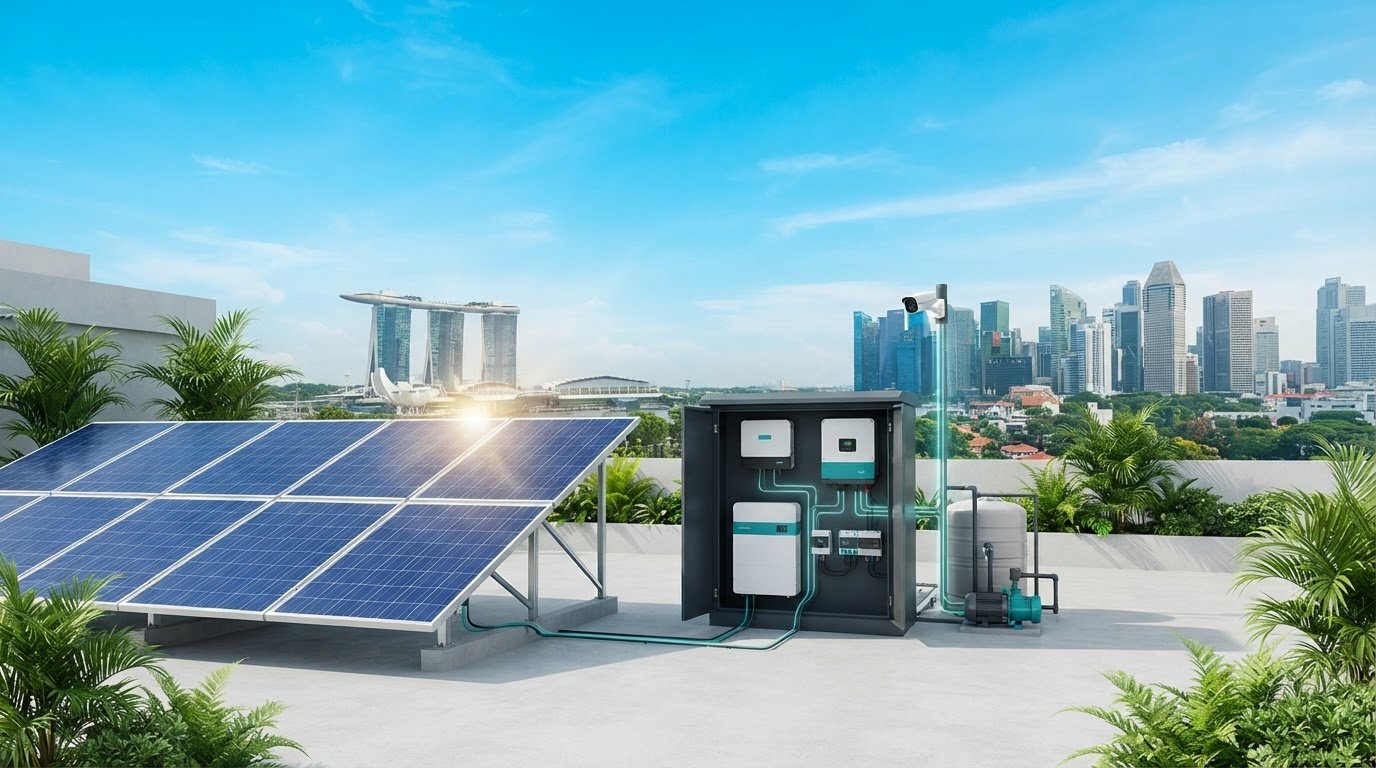
What if the battery with the highest capacity still can’t keep an off-grid system reliable? Battery sizing depends on the loads it must serve, the energy solar panels can generate, conversion losses and periods without adequate sunlight. That’s why off-grid solar battery storage needs to be designed as part of the complete system, not selected in isolation.
It’s reasonable to start with storage: the battery determines how much energy is available when generation falls short. But rated capacity alone doesn’t show how much energy is usable or whether the battery can work properly with the inverter and charge controller. A mismatch can limit the performance of the whole system.
This guide explains how to relate project loads to usable battery capacity, compare storage options using relevant technical criteria, and assess the hardware required beyond the battery. It also maps the roles of solar panels, charge controllers, hybrid inverters and circuit protection in an integrated design. From water monitoring to CCTV applications, a methodical workflow helps project teams specify a system around its operating requirements.
Key Takeaways
- Design off-grid solar battery storage around project loads and energy requirements, not a preferred battery size.
- Distinguish nominal capacity from usable capacity when comparing battery options.
- Assess operating conditions, lifecycle data and electrical compatibility alongside capacity.
- Separate critical loads from deferrable loads before estimating storage requirements.
- Consider the complete hardware path, including solar panels, charge controllers, hybrid inverters and circuit protection.
What Off-Grid Solar Battery Storage Does, and Where Its Limits Begin
Off-grid solar battery storage is one component in an electrical system designed to supply energy independently of a utility connection. Solar panels generate electricity, the battery stores some of that energy for later use, and power-conversion equipment delivers electricity in a form suitable for connected loads. The battery shifts energy across time; it doesn’t generate energy or define the system on its own.
Definition: Off-grid battery storage is the usable electrical energy held for later delivery within a system designed to operate without relying on a utility supply.
This distinction matters. A battery’s capacity alone can’t establish whether a project will meet its energy needs. The answer depends on the loads, when they operate, how much generation is available, and how much of the battery’s rated energy can be used within its operating limits. A general overview of home energy storage systems provides broader context on storage’s role, but project design still requires inputs specific to the system.
Off-grid operation versus grid-connected backup
An off-grid system is designed to supply its loads without depending on a utility connection. A grid-connected backup system, by contrast, normally operates alongside a utility supply and uses stored energy to serve selected loads when that supply is interrupted. Hybrid equipment can support different operating arrangements, but the project’s intended mode must be clear in the design.
The objective changes the storage specification. A continuously independent supply must be assessed against the loads and generation available throughout expected operating conditions. Backup design centres on the loads that must remain powered during an interruption and the required backup period. These are different design cases, so a battery selected for one shouldn’t automatically be assumed suitable for the other; for instance, providers such as Bright Earth Solar configure dedicated battery storage systems tailored specifically to whether a property needs standalone power or seamless backup during an outage.
What determines practical system autonomy?
Autonomy describes how long a system can support its defined loads under specified conditions. It depends on three connected inputs:
- Load profile: Which equipment operates, its energy demand, and the timing and duration of use.
- Available generation: The solar energy the array can supply under the project’s operating conditions.
- Usable stored energy: The portion of battery capacity available to serve loads, accounting for the battery’s operating limits and system conversion.
Consider a remote monitoring installation. Its design starts with the equipment that must remain active and its operating schedule, not an assumed battery size. If generation falls below consumption over time, stored energy will be drawn down. A larger battery can provide a temporary reserve, but it can’t compensate indefinitely for inadequate generation. Load reduction, additional generation, or a different operating objective may need to be considered.
There is no single autonomy figure that suits every project. Calculate requirements from the documented load profile, expected generation and usable battery energy, then assess how those inputs interact under the conditions the system is designed to handle. This project-specific basis prevents nominal battery capacity from being mistaken for guaranteed operating time.
How Off-Grid Solar Battery Storage Fits Into the System
Off-grid solar battery storage operates within a connected electrical architecture. Energy flows from photovoltaic (PV) modules to a charge controller, then into the battery. From there, power may supply compatible DC loads or pass through an inverter to serve AC loads. Circuit protection and correctly selected wiring support safe, coordinated connections throughout the system.
Generation produces energy, control regulates charging, storage shifts energy availability, and conversion supplies the form of power required by the loads. Each function depends on the surrounding components. Storage helps manage the variability of solar generation, but the project’s electrical design determines how each component is configured and how they operate together.
From solar panels to stored energy
Solar panels produce direct-current (DC) electricity. A charge controller sits between the PV array and battery, managing the charging process in line with the connected equipment’s electrical requirements. This stage isn’t simply a cable connection: the array and controller must be configured for the battery system they serve.
Many controllers use maximum power point tracking (MPPT). MPPT adjusts the array’s operating point to make use of available PV power as conditions vary. Its role is to manage the PV-to-battery charging interface, not to increase the energy the panels can generate beyond available sunlight.
From battery output to usable electrical loads
The battery stores DC energy. If the project includes AC equipment, an inverter converts DC power into AC output suitable for those loads. Its electrical input must suit the battery system, while its output must align with the connected equipment’s requirements. DC loads may follow a different path, so the load inventory affects the architecture.
Circuit protection belongs in the design from the outset. Protection devices are placed on relevant circuits to help manage electrical faults and protect connected conductors and equipment. Their selection and placement depend on the circuit, components and system configuration; they aren’t interchangeable accessories to add after sizing is complete.
Review the whole path, not just adjacent components. Confirm that the PV array configuration suits the controller, that controller and battery requirements align, and that the inverter suits both the DC source and intended AC loads. Wiring, connection methods and protection-device ratings also require technical review for the project. A mismatch at any interface can constrain the system even when individual components appear suitable.
For projects such as monitoring installations, this component view helps translate load requirements into a coordinated hardware specification. SM Solar supplies solar system hardware, including panels, charge controllers, batteries, hybrid inverters and circuit protection, supporting designs that account for generation, storage, control and conversion together.
How to Compare Off-Grid Battery Storage Options
Compare batteries against the project’s operating requirements, not a headline capacity or chemistry label. For off-grid solar battery storage, the useful comparison is whether a battery can deliver the required energy under the project’s conditions and work with the charge controller and inverter. SM Solar supplies lithium LiFePO4 batteries. Assess other battery categories using current, product-specific manufacturer documentation rather than assumptions about an entire chemistry.
Use a consistent comparison framework. Record each specification, the conditions under which it applies and any limits that affect the project.
| Comparison factor | What to examine |
|---|---|
| Usable capacity | Nominal capacity, manufacturer-stated usable energy and any stated discharge limits. |
| Operating conditions | Manufacturer limits for charging and discharging, including the conditions under which published figures apply. |
| Lifecycle data | Cycle-life or retention claims, with the test conditions and definitions shown alongside them. |
| System compatibility | Battery voltage and charging requirements against the controller, inverter and system configuration. |
Compare battery chemistry against the application
LiFePO4 is an option in SM Solar’s battery range, but chemistry alone doesn’t determine suitability. Start with the application: identify the required energy, operating pattern and equipment interface, then compare product documentation against those requirements. If considering other chemistries, use the same criteria and avoid generalising performance from one model to every battery in that category.
Manufacturer operating conditions are essential context. A cycle-life statement, for example, is meaningful only with its stated test conditions and definition. Compare like with like. If two specifications use different conditions, their figures aren’t directly equivalent. Record the source document and conditions with each entry so the selection remains traceable.
Nominal capacity, usable capacity and operating limits
Nominal capacity is the battery’s stated rated capacity. Usable capacity is the energy available for the application within specified operating limits. These are related, but they’re not interchangeable. The manufacturer’s documentation establishes how capacity is defined and the conditions under which it applies.
Depth of discharge (DoD) describes how much of a battery’s capacity has been discharged. A stated DoD limit affects the amount of energy available for use, so compare usable capacity rather than treating the full nominal rating as available. Don’t infer a universal usable fraction: the applicable limit depends on the product documentation and system configuration.
For a practical selection, match each candidate’s usable energy and operating limits to the project’s load requirements, then check compatibility with the charging and conversion equipment. Treat lifespan and retention as product-specific claims, not fixed chemistry-wide promises. This keeps the comparison grounded in verifiable specifications and relevant to the actual system.

How to Size Off-Grid Solar Battery Storage for a Project
Specify storage only after the project’s loads and generation have been assessed. Battery selection comes later. This sequence makes the design traceable to actual operating requirements, whether the system serves monitoring equipment, CCTV or water-related loads.
Storage sizing must follow the load and generation assessment, not precede it.
- Inventory the loads. List each device, its electrical demand and operating schedule. Use metered consumption or project records where available. Mark which values are measured and which are estimates, and record the source of each estimate.
- Classify load priority. Separate critical equipment from deferrable loads. For a monitoring project, continuous sensing or communications may be critical, while a non-essential load could be scheduled for periods of stronger generation or excluded during constrained operation. The project owner defines these priorities.
- Establish the operating requirement. Define when loads must run and the autonomy objective: how long the system should support the selected loads without sufficient solar input. Avoid assuming every load runs continuously or that every project requires the same autonomy period.
- Assess generation over the operating period. Use project-specific solar generation information and account for periods when generation may be reduced. Compare the energy expected from the array with load demand over the same period, rather than relying on an average that hides low-generation intervals.
- Translate the assessment into storage needs. Estimate the energy required during periods when generation cannot meet demand, then relate that requirement to the battery’s manufacturer-stated usable capacity and operating limits. The result is a design requirement, not a guarantee of supply under every condition.
Build a project load profile
Make the load record detailed enough to show timing, not just total consumption. For each device, note operating hours, duty cycle, startup or intermittent use where relevant, and whether its demand is measured or estimated. Identify critical monitoring, CCTV, water-quality or water-monitoring equipment when it applies to the project. This profile provides the basis for prioritisation and makes assumptions visible for later review.
Translate demand into a storage specification
Compare the required stored energy with usable battery capacity, not nominal capacity alone. Then cross-check the candidate battery against expected solar generation, charge-controller requirements and inverter input and output needs. Review how the design responds to low-generation periods and document any backup strategy or load-shedding approach. Neither storage capacity nor a backup plan should be treated as a promise of uninterrupted operation.
For a coordinated specification, align the load assessment with the panels, batteries, charge controllers, hybrid inverters and circuit protection in the design. Explore off-grid system integration with SM Solar when developing the project’s hardware requirements.
Specify Off-Grid Solar Battery Storage With SM Solar
Once the load profile, autonomy objective and generation assessment are established, translate them into a coordinated hardware specification. SM Solar supplies off-grid system components wholesale and provides system integration, installation and after-sales maintenance. The battery is one part of that package. Its requirements need to align with the solar array, charge control, power conversion and circuit protection.
Coordinate the hardware package around the design
Use the project design as the basis for component selection. Match the battery’s usable capacity and charging requirements to the load profile and expected energy supply. Then align the charge controller with the PV array and battery, and the hybrid inverter with the battery and required loads. Specify circuit protection for the relevant system circuits rather than treating it as an accessory chosen after the other equipment.
SM Solar supplies lithium LiFePO4 batteries, monocrystalline solar panels, solar charge controllers, hybrid inverters and solar circuit protection. Tie each component to a defined requirement, using manufacturer documentation to assess electrical compatibility. This keeps the specification coherent across the energy path instead of comparing parts in isolation.
For battery chemistry and protection considerations, consult SM Solar’s lithium battery and solar circuit protection information as part of the component review. The final selection should reflect the project’s electrical design and the specifications of the equipment being integrated.
Apply the approach to off-grid project requirements
Off-grid applications differ by load and operating schedule. SM Solar’s documented project examples include water-quality and water-monitoring applications, CCTV and noise monitoring. Each requires its own assessment of which equipment must operate, when it runs and how the system should respond when solar generation is limited. The application informs the design; it doesn’t establish a standard battery size or guarantee a particular operating outcome.
System integration and installation bring the specified hardware together within the project architecture. SM Solar also provides after-sales maintenance. In each case, the important design link is between project requirements and selected equipment: battery capacity and limits, panel generation, controller charging requirements, inverter output needs and protection-device selection. This component-level coordination is central to specifying off-grid solar battery storage for an actual application.
To move from design criteria to component selection, review SM Solar’s off-grid solar hardware and prepare the project load profile, generation assumptions and equipment requirements for the specification process.
Turn the Design Basis Into a Coordinated Specification
Turn the design basis into a procurement-ready brief. Record approved load priorities, operating schedules, autonomy objectives, generation assumptions, usable-energy requirements and electrical interfaces. Keep measured values distinct from estimates, and note any assumptions that still need resolution. This gives the project team a consistent basis for reviewing component choices and evaluating substitutions against the requirements.
That discipline applies across off-grid solar battery storage projects, including water-quality, water-monitoring and CCTV applications. SM Solar supplies batteries, charge controllers, solar panels, hybrid inverters and circuit protection devices. Its capabilities also include system integration, installation and after-sales maintenance, linking hardware supply with the broader project workflow without treating a battery as a complete system.
Use the brief to review the relevant equipment as a coordinated set, with each selection tied to a defined project requirement. Review SM Solar’s off-grid solar hardware range and use your project brief as the basis for a clear, project-specific specification.
Frequently Asked Questions
Can an off-grid solar battery system be expanded after installation?
Yes, if the existing equipment and system design support additional battery capacity. Expansion can be constrained by the inverter, charge controller, battery management system, wiring, protection devices and the manufacturer’s rules for connecting battery units. Before adding storage, review the installed equipment’s specifications and condition, then recalculate the system requirements. A compatible expansion may still require changes to settings or other components.
How does a battery management system support battery operation?
A battery management system (BMS) monitors battery operating parameters and manages functions defined by the battery manufacturer. Depending on the design, it may monitor cell voltage and temperature, control charging or discharging, and trigger protective limits. It doesn’t increase the battery’s rated capacity or replace correct system design. The battery documentation should specify how its BMS communicates or coordinates with the inverter and charging equipment, if applicable.
What happens to an off-grid battery when it reaches its discharge limit?
At its specified discharge limit, battery controls may restrict or stop further discharge to protect the battery. The effect on connected equipment depends on the system: loads may lose supply, or an inverter may shut down or signal a fault. The system must then recharge the battery before normal operation resumes. For off-grid solar battery storage, understand the configured cut-off and recovery behaviour from the battery and inverter documentation.
Can an off-grid solar system use a generator as backup?
Yes, a generator can be included in some off-grid designs, provided the inverter or charging arrangement supports it and the equipment is configured for the generator’s electrical output. The design must account for connection, switching, charging control, protection and safe operation. A generator doesn’t remove the need to size storage around the loads. Its role and operating procedure should be defined in the system plan.
How should battery storage be maintained in an off-grid system?
Follow the battery and equipment manufacturers’ maintenance instructions. Keep records of system alarms, operating conditions and any changes in observed performance, and inspect the installation for visible damage, corrosion or loose connections only where safe to do so. Don’t open sealed battery enclosures or alter electrical connections without appropriate technical competence. Maintenance intervals and permissible inspection procedures depend on the specific battery and system configuration.
Are off-grid solar batteries recyclable at end of life?
Many battery materials can be recovered through suitable recycling processes, but the correct route depends on the battery chemistry and local collection arrangements. Don’t place a spent battery in general waste or dismantle it. Keep it intact and follow the applicable battery collection or recycling instructions for your location. If a battery is damaged, handle it according to the manufacturer’s safety guidance and the relevant local disposal process.
Can different battery types be connected in the same system?
Only when the system and battery manufacturers explicitly allow the proposed combination. Different chemistries, models, ages or capacities can have different voltage characteristics, charging requirements and operating limits. Combining them without an approved design may cause uneven charging or operation outside specified conditions. Check the permitted configuration for the batteries, BMS, charge controller and inverter before making changes. Don’t assume batteries with similar nominal voltage are compatible.

